24 English 5.906-468.0 Rev. 00 (02/09)
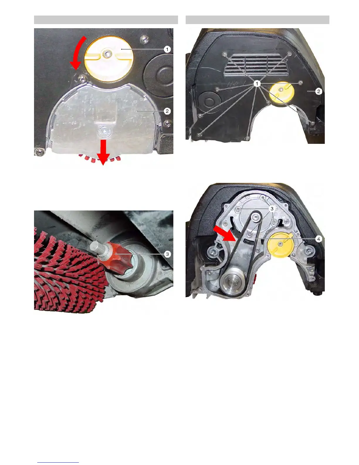
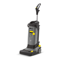
Î Raise the brush head.
Î Turn the lock of the bearing cover counter-clockwise.
Î Push the bearing lid down and remove.
Î Pull out the brush roller.
Î Insert the new brush roller and slide it onto the pickup mandrel.
Î Reassemble the bearing lid in the reverse sequence.
1 Lock, bearing lid
2 Bearing lid
3 Pickup mandrel
Î Remove the bearing lid from the brush roller mount (see Chap-
ter 5.10).
Î Unscrew the fastening screws of the drive belt cover and re-
move the drive belt cover.
Î Loosen the fastening screws of the brush motor.
Î Remove the drive belt.
Î Install the new drive belt, tension it and tighten the fastening
screws on the motor. The V belt tension is determined via the
position of the motor shaft (tensioning by raising the motor, e.g.
with a screwdriver, through the elongated hole beneath the mo-
tor shaft).
Note
The drive belt must be tensioned so that it can be deflected by a
strong thumb press to a max. of 5 mm (arrow) between the motor
shaft and the driven pulley.
1 Fastening screws (9x), drive belt cover
2 Drive belt cover
3 Fastening screws (4x), brush motor
4Drive belt
5.10 Replace the brush rollers on the BR brush head 5.11 Replace the drive belt