40 English
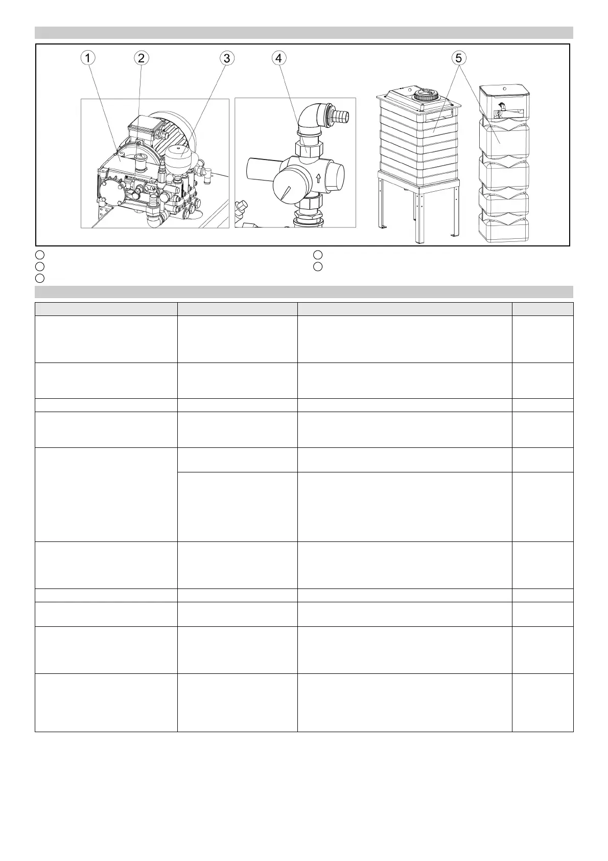
Machine room maintenance overview
1 High-pressure pump
2 Oil level indicator
3 Pressure tank
4 Pressure reducer
5 Fresh water tank
Daily maintenance plan
Assembly Activity Performed Target group
Emergency off button
Safety switch
Check Start the washing program, actuate an emergency-off
button or safety switch, the system must stop imme-
diately, then switch the system on again, see chapter
“Switching on again after an emergency off”.
Operator
Signs with operating instructions
and intended use
Check the instructions for
self-service customers (self-
service systems only)
Check all signs for completeness and legibility.
Replace any damaged signs.
Operator
Cleaning and care agent reservoirs Check the filling level Refill or replace as necessary. Operator
High-pressure hoses from the
high-pressure pump to the wash-
ing bay
Check Check the hoses for damage. Replace faulty hoses
immediately. Danger of accident.
Operator
Spray nozzles/sieves Checking for clogging Visual inspection (assess the spray pattern), clean if
necessary.
Operator
Eliminate clogging Warning, do not swap over the nozzles.
Unscrew nozzles individually to avoid mixing them
up.
Clean with compressed air or insert in a detergent
solution and then clean with a brush or needle. Screw
in the nozzles again.
Operator
Light sensors Check for soiling, clean if
necessary
For light soiling, wipe the light sensors with a damp
cloth without detergent under light pressure. In the
event of heavy soiling, spray the cloth with a gentle
detergent.
Operator
Limits switches Visual inspection Check for mechanical damage and firm seating. Operator
Side brushes, roof brush, wheel
brushes
Check for foreign bodies Visual inspection, remove any foreign bodies, clean
dirty brushes with a high-pressure cleaner.
Operator
Rinsing and spray circuits Check the water supply In washing mode, check that sufficient water for vehi-
cle washing is available.
Too little water of no water can damage the vehicle
being washed.
Operator
Positioning light Function test Interrupt the “Position 1” and “Position 2” light sen-
sors, for the position of the light sensors see chapter
“Front maintenance overview”.
The positioning light must display corresponding sig-
nals.
Operator
 Loading...