GB - 10
3.3 Connection of Power Circuit
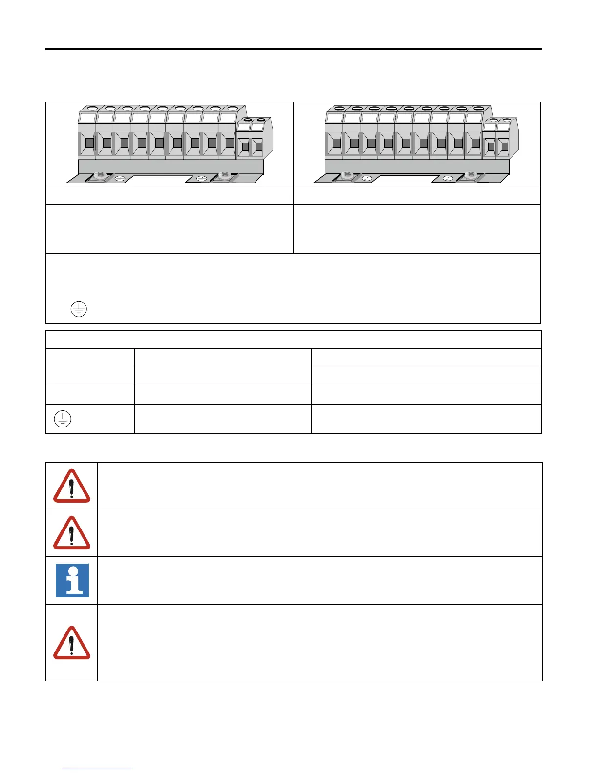
3.3.1 Terminal Strip X1A
Installation and Connection
N/L2 L3 PB U V W
T1 T2
--++
L1
L2 L3 PB U V W
T1 T2
-- ++
L1
Terminal strip X1A/ 230 V class suitable for Terminal strip X1A/ 400 V class suitable for
• 180…260 V AC / 1-phase (L1/N) • 305…528 V AC / 3-phase (L1, L2, L3)
• 180…260 V AC / 3-phase (L1, L2, L3) • DC supply 420…720 V DC (++,- -)
• DC supply 250…370 V DC (++,- -)
• ++, PB Braking resistor
• U, V, W Motor
• T1, T2 Temperature sensor / switch (see chapter 3.3.6)
•
Protective earth connection
Permissible cable cross-sections and tightening torques of the terminals
Terminals Perm. conductor cross-section Tightening torque
L1…W 0.2…6 mm² (AWG 24-10) 0.6 Nm (5 lb inches)
T1, T2
0.1…2.5 mm² (AWG 30-14)
0.6 Nm (5 lb inches)
PE Screw M4 1.3 Nm (11.5 lb inches)
3.3.2 Wiring instructions
Absolutely observe the connecting voltage of the KEB COMBIVERT. A 230V-unit will
be immediately destructed on a 400V-power supply.
Never exchange the mains and motor cables.
Some countries demand that the PE-terminal is directly connected to the terminal
box (not over the mounting plate).
Separate supply of the control
Without further cooling measure a separate supply of the control is not permissible
during a longer period, because the interior fan is not controlled here. The occuring
heat accumulation causes an accelerated aging of the capacitors and thus for a
reduction of the economic life time.

 Loading...


