GB - 13
An external temperature sensor/switch can be connected to the terminals T1,
t2 . The supply unit switches off with the error message E.OH during tripping.
As standard the evaluation at terminals T1 and T2 is switched off and must be
activated if necessary (application mode Pn.12=“7“).
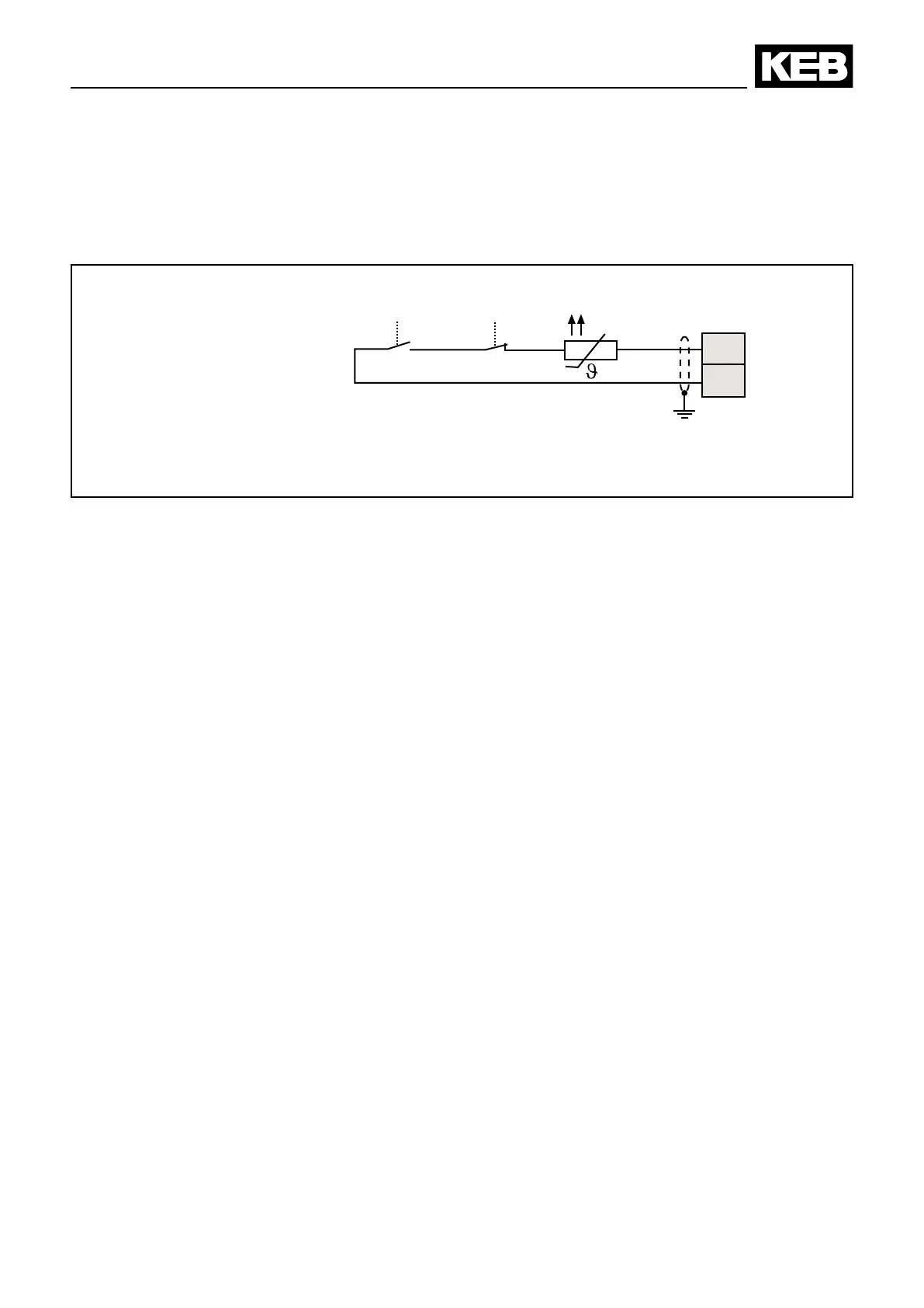
3.2.4 Connection of a Temperature Detection
other
PTC
Temperature sensor (PTC)
Tripping resistance 1650 Ω…4 kΩ
Reset resistance 750 Ω…1650 Ω
(acc. VDE 0660 Teil 302)
Installation
other
3.3 Instructions of an EMC-conform Installation
• To avoid coupled-in noise, separate
a) Line-supply cables,
b) Motor lines of frequency inverters/servo power controller,
c) Lay control and data lines (low-voltage level <48
V), with a distance of
at least 15 cm.
• In order to maintain low-resistance high frequency connections, earthing and
shielding, as well as other metallic connections (e.g. mounting plate,
installed units ) must be in metal-to-metal contact with the mounting plate,
over as large an area as possible. Use earthing and equipotential lines with
a section as large as possible (min. 10
mm
2
) or use thick earthing strips.
• If external interference suppression lters are used, then these must be
installed as close as possible to (<30
cm from) the interference source and
in metal-to-metal contact with the mounting plate, over as large an area as
possible.
• Always equip inductive control elements (contactors, relays etc.) with
suppressors such as varistors, RC-elements or damping diodes.
• All connections must be kept as short as possible and as close as possible
to the earth, as free oating lines work as active and passive aerials.
• Keep connection cables straight (do not bundle). Install a non-assigned wire
on both sides of the protective conductor.
• The ow and return circuit must be twisted when the lines are not shielded,
in order to dampen common-mode noise.
• As a general principle use metal cable glands with shield connection.

 Loading...