GB - 14
Installation and connection
4. Installation and connection
4.1 Control Card Version C
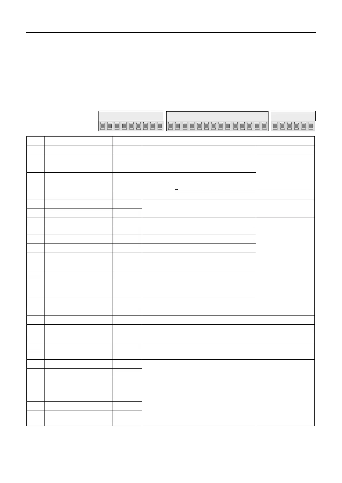
4.1.1 AssignmentoftheTerminalStripX2A
X2A
PIN Function Name Explanation
1...4 without function - - - -
5 Analog output 1: ANOUT1
Analog output of the DC output current
0…10 VDC ^ 0…200 %
Voltage range:
0…±10 V
Ri: 100 Ω
Resolution: ±10Bit
6 Analog output 2: ANOUT2
Analog output of the DC voltage
0…10 VDC ^ 0…1000 VDC
7 without function - - - -
8 Analog mass COM
Mass for analog in- and outputs
9 Analog mass COM
10 without function - - I1 -
Ri: 2,1 kΩ
Scan time: 4 ms
11 without function - - I2 -
12 without function - - I3 -
13 without function - - I4 -
14 Slave input I5 only interconnected operation
00.R5.0DM-I000
15 without function - - I6 -
16 Start ST Thyristors switched through
Error reset during opening
17 Reset RST Reset; only possible in fault condition
18 Transistor output 1 O1 „Run“; is set, if the thyristors are switched trough
19 Transistor output 2 O2 „Error" is set, if the unit switched off on error
20 24 V-output Uout Power supply for digital inputs I
max: 100 mA
21 without function - - - -
22 Digital ground 0V
Reference potential for digital in-/outputs
23 Digital ground 0V
24 Relay 1 / NO contact RLA
Relay output
Ready for operation signal
max. 30 V DC
0.01…1 A
25 Relay 1 / NC contact RLB
26 Relay 1 / switching
contact
RLC
27 Relay 2 / NO contact FLA
Relay output
phase error warning
28 Relay 2 / NC contact FLB
29 Relay 2 / switching
contact
FLC
123456789
10 11 12 13 14 15 16 17 18 19 20 21
22 23 24 25 26 27 28 29

 Loading...