GB - 15
4.1.2 Connection of the control
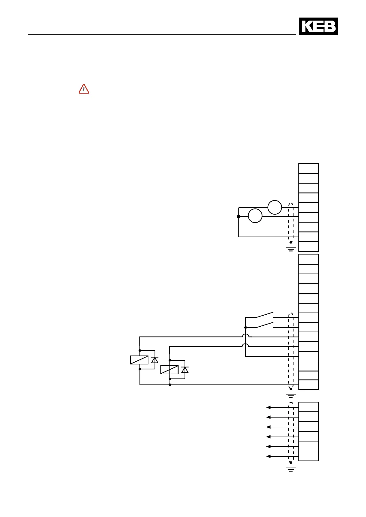
In order to avoid malfunctions caused by interference voltage supply at the
control inputs, the following instructions must be observed:
• Use shielded/drilled cables
• Lay shield on one side of the inverter onto earth potential
• Lay power and control cable separately (about 10…20 cm distance); lay
cables in a right angle
EMC
max. 30 V DC
0,01…1 A
max. 30 V DC
0.01…1 A
max. 50 mA DC
for both outputs
Analog output
0…10 V DC / 5 mA
Installation and connection

 Loading...