8
Changing the Configuration
Each measurement function and operation has the
default settings that are listed in Table 18. For example,
the default settings for DC voltage are as follows:
• Measurement speed (integration time)
Normal, 1
power line cycle.
• Digital filter
Advanced, 10 readings, 1% noise tol-
erance, moving average.
• Display resolution
6.5 digits.
If these settings are not sufficient for your application,
they can be changed through configuration menus. For
example, to configure the DC voltage function to store
high speed measurements, follow these steps:
1. Press CONFIG key and then the DCV key to view
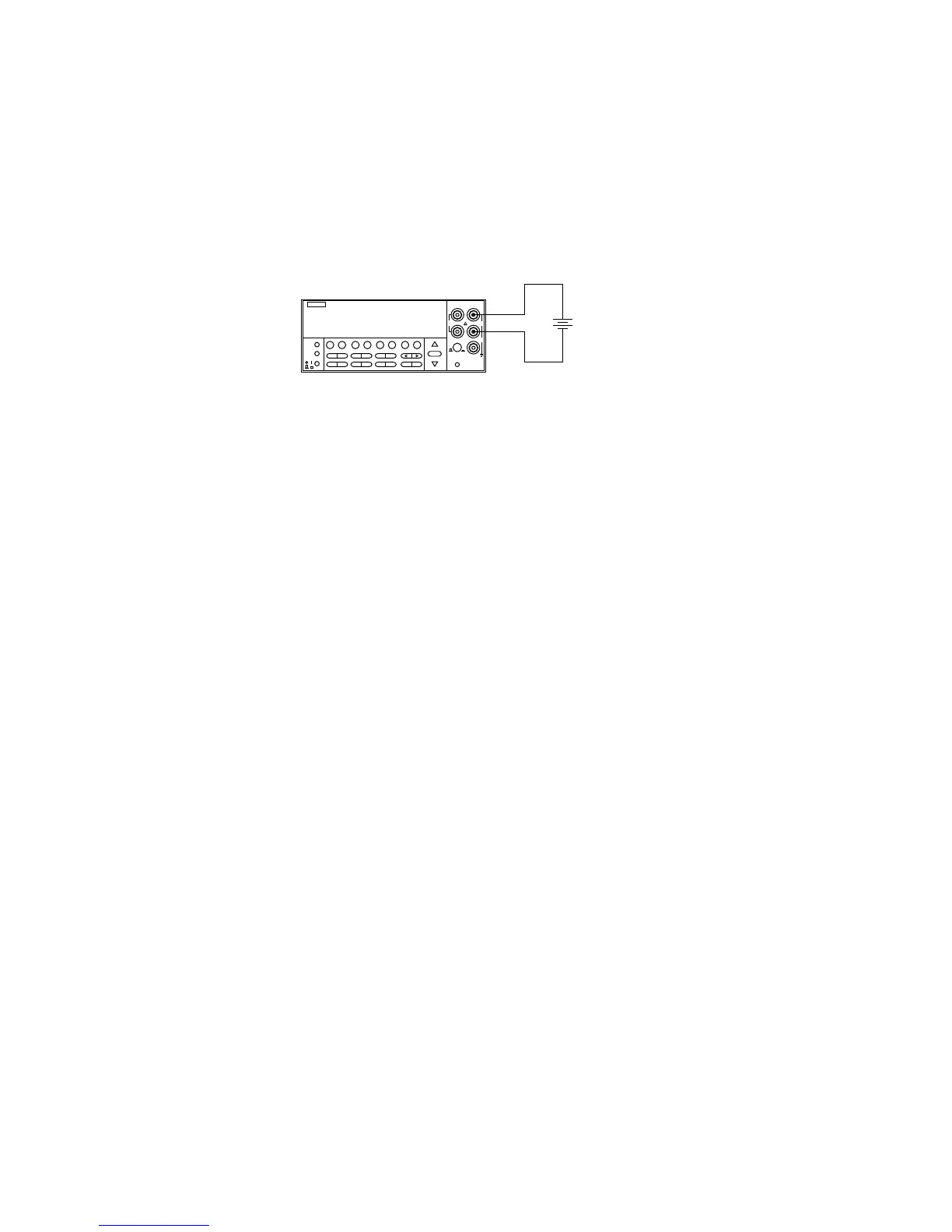
Figure 1. Typical DC voltage connections
NEXT
DISPLAY
PREV
POWER
DCV ACV DCI ACI Ω2 Ω4 FREQ TEMP
REL TRIG STORE RECALL
INFO LOCAL CHAN SCAN CONFIG MENU EXIT ENTER
RANGE
AUTO
FILTER MATH
RANGE
2001 MULTIMETER
SENSE
Ω 4 WIRE
HI
INPUT
LO
INPUTS
CAL
500V
PEAK
F
R
FRONT/REAR
2A 250V
AMPS
350V
PEAK
1100V
PEAK
Model 2001
Caution : Maximum Input = 1100V peak
DC Voltage
Source
Input Resistance = 10MΩ on 1000V and 200V ranges ;
> 10GΩ on 20V, 2V and 200mV ranges.
= 1MΩ on DCV peak spikes measurement.