EasyManua.ls Logo

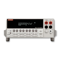
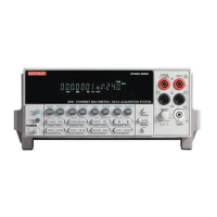
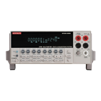
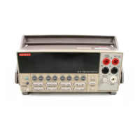
Keithley 2110 User Manual

Keithley 2110
221 pages
To Next Page IconTo Next Page
Page #1 background imageLoading...
Page #1 background image
Reference Manual
2110-901-01 Rev. C / August 2013
*P211090101C*
2110-901-01
www.keithley.com
Model 2110 5½ Digit Multimeter
A Tektronix Company
A Greater Measure of Confidence

Table of Contents

Other manuals for Keithley 2110

Questions and Answers:

Keithley 2110 Specifications

General IconGeneral
Model2110
DC Voltage Range100 mV to 1000 V
AC Voltage Range100 mV to 750 V
ContinuityYes
Diode TestYes
CategoryDigital Multimeter
Display5.5 digit
DC Current Range100 µA to 3 A
AC Current Range100 µA to 3 A
Resistance Range100 MΩ
Frequency Range3 Hz to 300 kHz
Frequency Accuracy0.01% + 1 count
Capacitance Range1 nF to 100 µF
Capacitance Accuracy1% + 5 counts
ConnectivityUSB, GPIB (optional)
Dimensions88 mm
Power Supply100 V to 240 V AC, 50/60 Hz
DC Voltage Accuracy±0.012% + 2 counts

Summary

Section 1 Introduction

Welcome

General welcome message for new users of the Model 2110.

Capabilities and features

Overview of the Model 2110's key features and performance specifications.

General information

General details about the instrument, including serial number and dimensions.

Measurement ranges and functions

Details on the available measurement ranges and functions for the Model 2110.

Power-on settings

Information on the instrument's default settings upon power-on.

General specifications

Technical specifications covering electrical, environmental, and safety aspects.

Section 2 General overview

Turning your instrument on and off

Procedures for powering the instrument on and off, and connecting line power.

Front panel overview

Description of the instrument's front panel controls, display, and terminals.

(1) Display

Explanation of the primary and secondary display areas and indicators.

(3) The function and operation keys

Details on using the front panel keys for selecting functions and operations.

(7) Menu overview

Overview of the instrument's menu structure for configuration and settings.

Rear panel overview

Description of the instrument's rear panel connectors and features.

(3) USB connection

How to connect and use the instrument's USB port for communication.

(5) AC line receptacle, power line fuse, and line voltage setting

Details on power input, fuse location, and line voltage configuration.

System operations

Operations related to system settings like display, beeper, and language.

Viewing errors in the error queue

Procedure to view and interpret instrument error messages.

Section 3 Basic DMM operation

Basic measurement functions

Overview of the Model 2110's measurement capabilities.

Voltage measurements

Detailed steps for measuring DC and AC voltages with the instrument.

Current measurements

Procedures for measuring DC and AC current accurately.

Resistance measurements

Methods for measuring resistance using 2-wire and 4-wire techniques.

Triggering and data buffer

Managing measurement triggers and storing readings in the data buffer.

Enhancing measurement performance

Settings and features to optimize measurement speed and accuracy.

Autozero

Controlling autozero to correct for instrument drift.

Range selection

Methods for setting measurement ranges or using autorange.

Resolution and integration time

Adjusting display resolution and integration time for measurements.

Math operations

Overview of available mathematical operations like Percent, Average, Null.

Section 4 Theory of operation

AC voltage measurements and crest factor

Explains RMS values and crest factor for AC waveforms.

DMM resistance measurement methods

Explains the constant-current method for resistance measurement.

Reference junctions

Explains thermocouple reference junctions (real and simulated).

Accuracy calculations

Details how to calculate DC and AC measurement accuracy.

Section 5 Remote commands

Programming syntax

Rules for constructing SCPI commands for instrument control.

IEEE-488.2 common commands

Standard SCPI commands like *CLS, *RST, *IDN? for instrument control.

SCPI command subsystem reference

Overview of SCPI subsystems for instrument configuration.

CALCulate subsystem summary

Summary of commands for math and calculation functions.

SENSe subsystem summary

Summary of commands for configuring measurement parameters.

SYSTem subsystem summary

Summary of commands for system settings and status.

TRIGger subsystem summary

Summary of commands for controlling trigger events.

Section 6 Troubleshooting guide

Troubleshooting

General information to help diagnose and resolve instrument issues.

Running a self-test

Procedure for running instrument self-tests to check hardware functionality.

Error codes

List and explanation of execution and self-test error codes.

Appendix A Maintenance

Introduction

Overview of operator-performable maintenance procedures.

Line fuse replacement

Procedure for replacing the instrument's power line fuse.

Current input fuse replacement

Procedure for replacing the instrument's current input fuses.

Upgrading the firmware

Instructions for updating the instrument's firmware.

Appendix B Status model

Overview

Explanation of the instrument's status reporting structure.

Status byte and SRQ

How the Status Byte Register and Service Request (SRQ) function.

Status register sets

Structure of instrument event registers and enable registers.

Clearing registers and queues

Commands to reset status registers and clear queues/buffers.

Service request

How service requests (SRQ) are generated and controlled.

Standard Event Register

Bit definitions and descriptions for the Standard Event Register.

Questionable Data Register

Bit definitions for conditions like range overload and limit failures.

Appendix C Communication interface

Communication interfaces

Connecting instruments via USB and GPIB interfaces.

Selecting an interface

Choosing between GPIB and USB for remote instrument control.

USB communications

Setup and usage instructions for USB connections.

Addressing instruments with VISA

Using VISA resource strings for instrument communication.

Addressing instruments using USB

Format of USB VISA resource strings for instrument identification.

Addressing instruments through GPIB

Using VISA resource strings for GPIB communication.

Supplied software

List of software components included with the instrument.

Keithley I/O layer

Details on the Keithley I/O Layer software package and its components.

How to install the Keithley I/O Layer

Procedures for installing the Keithley I/O Layer software.

Related product manuals