2: General overview Model 2110 5½ Digit Multimeter
2-18 2110-901-01 Rev. C/August 2013
Keys, menus, and selection Description
Select communication interface. Refer to Rear panel connection
details (on page 2-19).
Enter or change GPIB address.
Rear panel overview
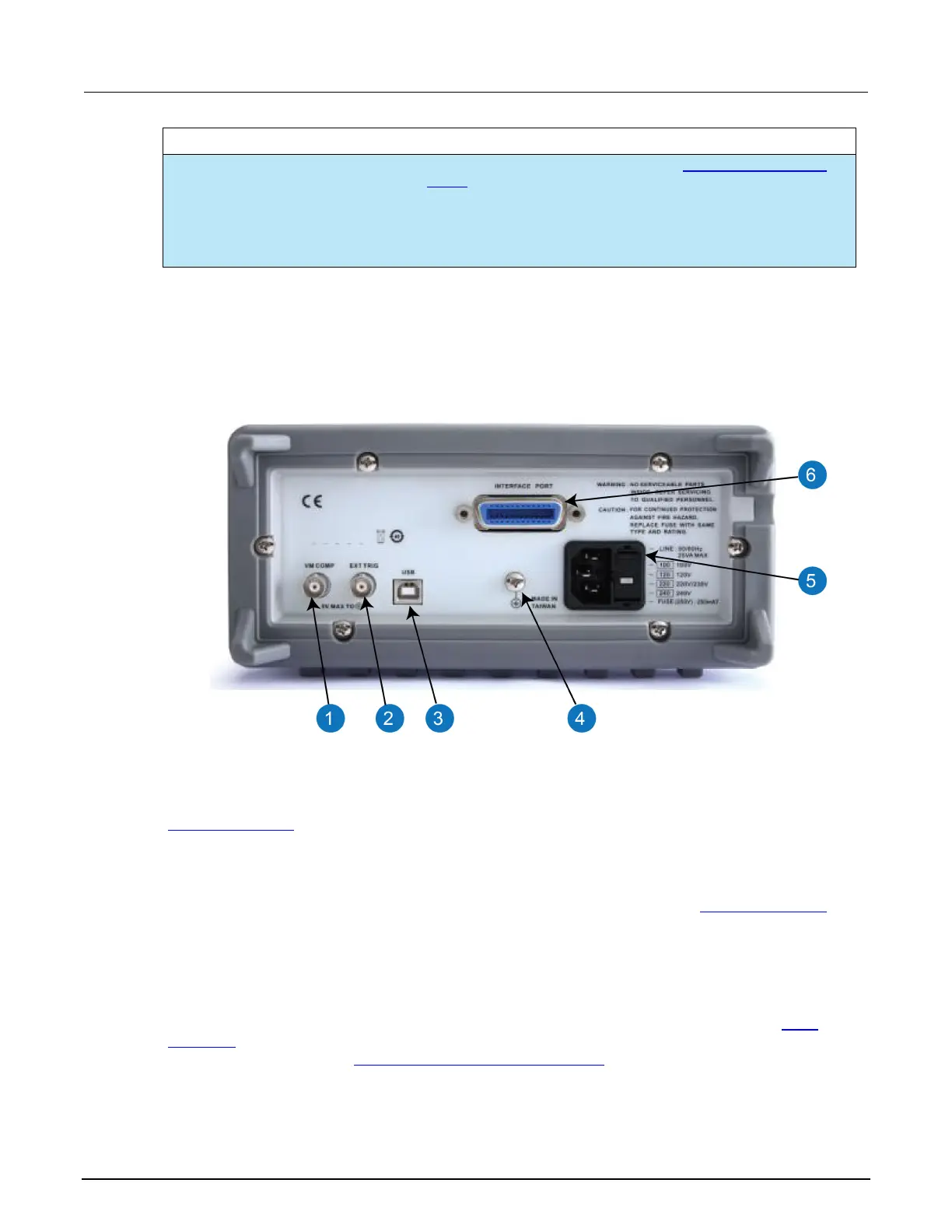
The rear panel of the Model 2110 is shown in the following figure. This figure includes important
abbreviated information that should be reviewed before using the instrument.
Figure 13: Rear panel
(1) Voltmeter complete output terminal (VM COMP)
The VM COMP output terminal outputs a low-true pulse after each completed measurement. Refer to
External triggering (on page 3-31
) for details.
(2) External triggering input terminal (EXT TRIG)
Use the EXT TRIG input terminal when choosing external triggering. Refer to External triggering (on
page 3-31) for details.
(3) USB connection
Use the USB connector to connect the instrument to a remote computer. You can use this connection
to switch the instrument to remote mode instead of using the front-panel control. Refer to
USB
connector (on page 2-19) for details. For information on using the USB connector as a PASS/FAIL
output for limit testing, see Pass/fail output from USB connector (on page C-5).