5½ Digit Multimeter Reference Manual Section 2:
2110-901-01 Rev. C/August 2013 2-19
(4) Protective earth (safety ground)
Ground screw for connection to protective earth (safety ground). Connect to protective earth using
recommended wire size (#16 AWG or larger).
(5) AC line receptacle, power line fuse, and line voltage setting
Provides:
• AC line receptacle. Use to connect to AC power. Refer to Turning your instrument on and off (on
page 2-1) for details.
• Line voltage setting. Configured for line voltages of 100 V, 120 V 220 V, and 240 V. Refer to
Voltage selection (on page 2-2
) for details.
• Fuse. Contains the power line fuse. Refer to Line fuse replacement (on page A-1) for details.
(6) Interface port
If the optional GPIB connection is present in the interface port, you can connect the instrument to a
remote computer with an IEEE-488 cable. Refer to GPIB connector (on page 2-19
) for details.
Rear panel connection details
The following topics describe how to connect the cable connections for the communication interfaces.
To properly set up the communications interfaces after connection, see the information in
Communication interfaces.
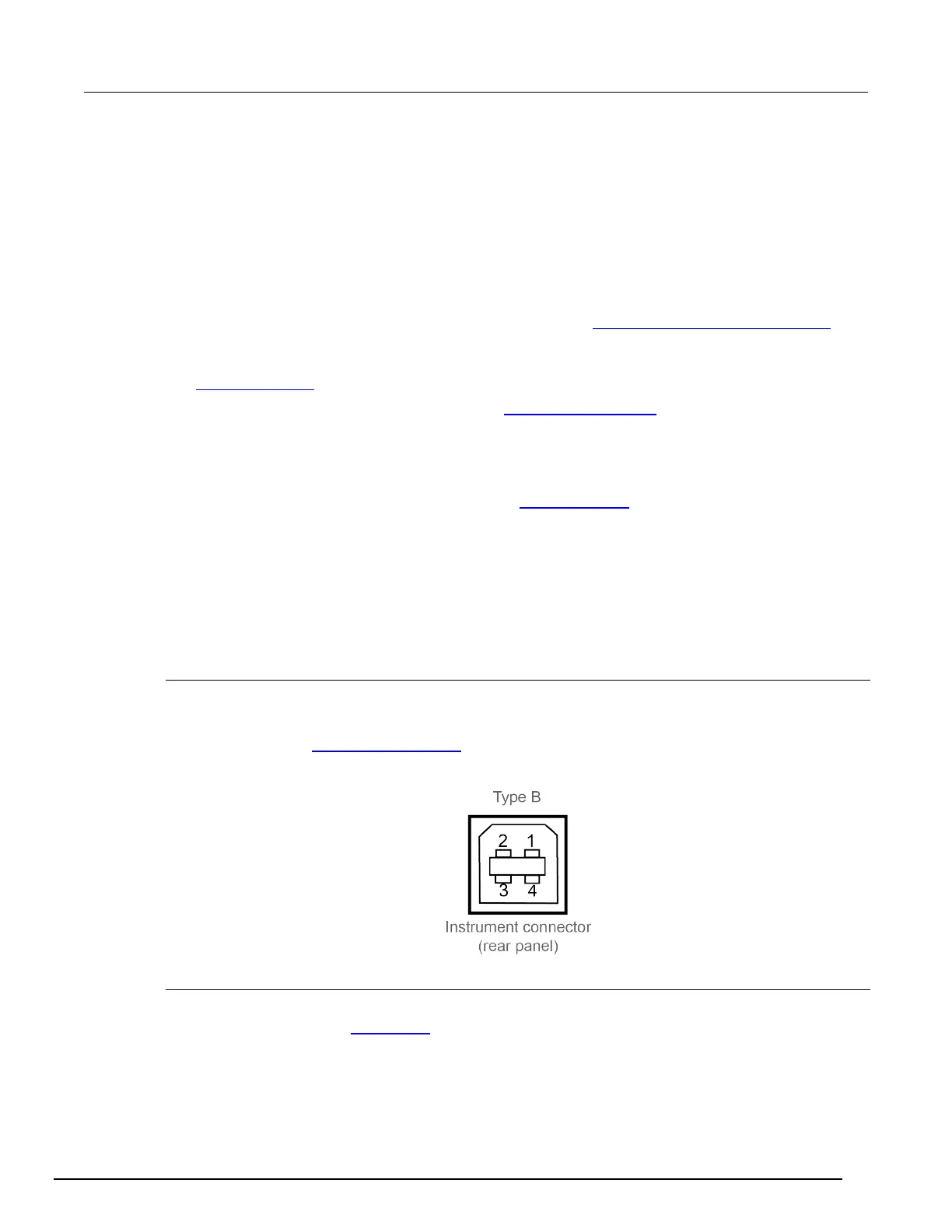
USB connector
The downstream Type B USB-2.0 receptacle located on the rear panel connects to a host.
Use the rear connector to communicate with the instrument over USB by sending the desired
commands. Refer to USB communications (on page C-1
) for information about using this connector.
Figure 14: USB connector
GPIB connector
To connect Model 2110 to the GPIB bus, use a cable equipped with standard IEEE-488 connectors,
as shown below. Refer to GPIB setup (on page C-7
) for information about using this connector.