System Switch/Multimeter User's Manual Section 9:
Series 3700 Module Schematics and Connections
-900-01 Rev. A / August 2007 9
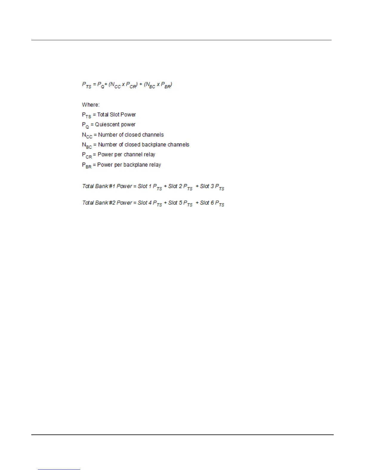
In order to determine whether or not a given quantity of relay operations can be performed, the
tables above must be used to calculate the total power required by applying the example
equations given below:
To check power consumption, each slot power must be computed. The slot power for slots 1
through 3 are added. Also, slot power for slots 4 through 6 are added. The results are called
bank powers, and should be compared with the maximum limits. Some example calculations
follow.