System Switch/Multimeter User's Manual Section 2:
-900-01 Rev. A / August 2007 2
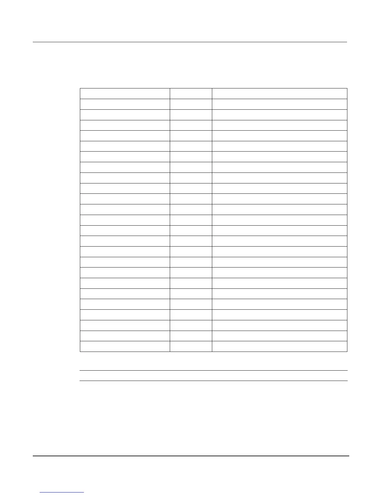
The bottom line of the display (4) contains the attribute symbols. The symbols that appear are
dependent on whether the attribute exists for the selected function. If the symbol has also
contains a value, the third column in the table indicates the value definition. The following table
indicates the DMM attribute symbols that may appear on the front panel.
Front panel DMM attribute
AUTO or n, here n equals the range
n, where n equals the nplc
+ for ON, 1 for ONCE, or 0 for OFF
for ON or – for OFF
– for OFF
– for limits disabled
n, where n indicates the threshold
n, where n indicates the aperture setti
ng
– for OFF
ermocouple sensor B
-wire RTD
-wire RTD
simulated reference junction
internal reference junction
external reference junction
NOTE To access the main menu, press the MENU key.