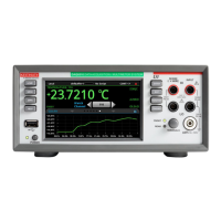
The physical connections for the front panel are shown in
the following fi gures. Note that you must use either the front
terminals or rear terminals—you cannot mix connections. The
front-panel and rear-panel connections are safety banana jacks.
The example in this guide shows you how to make connections
to the front panel and short the connections.
For this example, you can make the connections with the Model
1756 Standard Test Lead Kit.
1. Make sure the front panel POWER switch is off.
2. Connect the red lead to the INPUT HI connection.
3. Connect the black lead to the INPUT LO connection.
Do not apply more than 1000 V
PEAK
to the INPUT terminals or
more than 350 V
PEAK
to the SENSE terminals. Failure to heed
this caution may result in instrument damage.
Do not apply more than 250 V
PEAK
between INPUT LO and
the AMPS input. Failure to observe this caution may result in
instrument damage.
Do not apply more than 3 A, 250 V to the input. This will
cause the AMPS fuse to open-circuit.
To prevent electric shock, test connections must be
confi gured such that the user cannot come in contact with
test leads or any device under test (DUT) that is in contact
with the conductors. It is good practice to disconnect DUTs
from the instrument before powering the instrument. Safe
installation requires proper shields, barriers, and grounding
to prevent contact with test leads.
Connections for testing

 Loading...