©2009 4Front Engineered Solutions, Inc.
January 2009 6004754F — HK and HK-S Hydraulic Dock Leveler, 3 Button — SafeTFrame
™
39
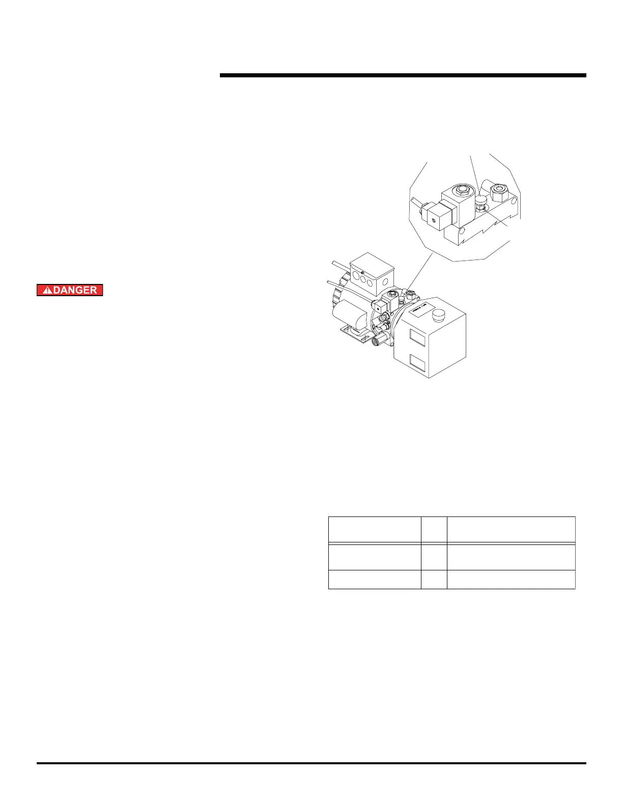
Needle valve
locking nut
Needle valve
adjusting screw
turn screw clockwise
to increase time
length of
dock leveler
12
6' & 8'
seconds 1 second
±
pit
size
19"
10'
23" 18
PARTS REPLACEMENT
Fig. 46
CONTROL BOX TRANSFORMER — 3 PHASE ONLY
When replacing the transformer make sure jumper wires
are installed per wiring diagrams, for appropriate phase
and voltage.
HYDRAULIC OIL HOSES
When removing hydraulic oil hose(s) remove from motor/
When installing hydraulic oil hose(s) attach to cylinder
motor assembly.
Be certain, before climbing into the dock leveler pit or
doing any maintenance or repair under the dock leveler,
that:
1) THE MAINTENANCE STRUT AND LIP LOCK ARE
SECURELY IN PLACE, [see Fig. 38] and
2) the power is disconnected and properly tagged or
locked off.
After replacing hose and/or motor pump assembly, run
pump/motor at least four (4) times with the maintenance
strut and lip lock in place. This is required to remove air
from the system. Check oil level and add oil if required.
Use extreme care when removing maintenance strut
and lip lock. Ramp and lip could move down rapidly if air
remains in the system. Run dock leveler four (4) times
through the complete operating cycle before placing
dock leveler into service.
MOTOR/PUMP ASSEMBLY
To set the downward speed of the ramp:
1.1 Loosen needle valve locking nut. See Fig. 46.
1.2
Turn valve in 1/4 turn increments only. “IN” clockwise
will increase time, “OUT” counterclockwise will
decrease time. Tighten needle valve locking nut.
below dock stop per chart at right.
Adjust valve “OUT” in 1/4 turn increments only to
achieve proper lowering time.
1.
1.
2.
1.
 Loading...