©2009 4Front Engineered Solutions, Inc.
January 2009 6004754F — HK and HK-S Hydraulic Dock Leveler, 3 Button — SafeTFrame
™
9
Frame
uprights
Rear hinge
assembly
2-1/2"
5"
2-1/2"
5"
5"
5"
2-1/2"
5"
2-1/2"
5"
Bevel groove weld locations
Pit
rear
curb
angle
Rear pit
curb angle
Pit side curb angle
Ramp
Rear
frame
angle
1/2"
1/2"
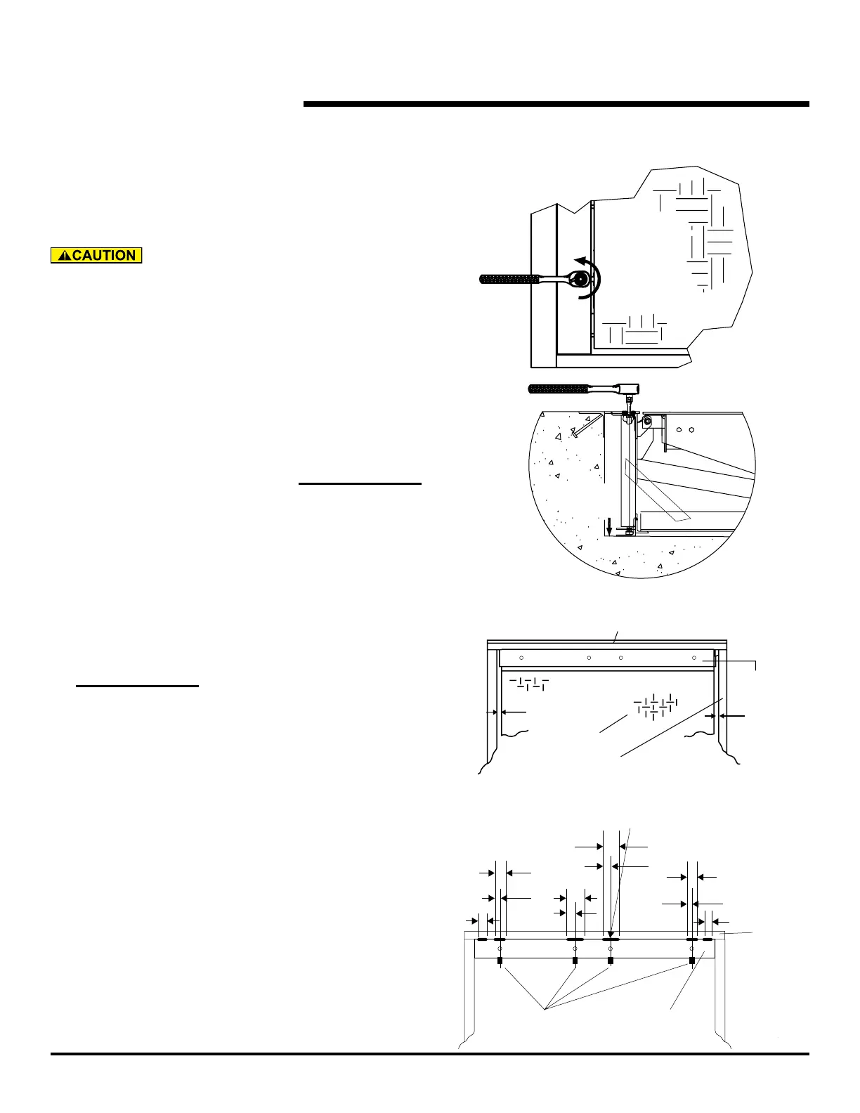
INSTALLATION, continued
LEVELING THE FRONT FRAME
at the lower end of the hinged lip assembly. See Fig.
14.
Before welding the dock leveler supports to the front
curb angle make sure that the dock leveler support legs
line up with the "V" pocket in the dock leveler support
angle. Move dock levelers support right or left for the
necessary alignment.
7. Tack
weld the front dock leveler supports to the front curb
angle with 3/16" welds as shown in Fig. 12.
8. With the lip pendant insert 24" long 1/2" extensions
between lip and lip rod onto dock leveler support leveling
screw. See Fig. 12. Using a 1/2" drive (1/2" ratchet or
impact tool) turn each leveling screw counter-clockwise
See Fig. 11.
9. Weld the rear frame angle to the rear curb angle using
1/4" bevel joints in the transition plate as your guide. See
Fig. 10.
counter-clockwise to 25-40 ft. lbs.
Fig. 9
Fig. 10
Raises
rear
angle
Leg
adjustment
Fig. 8