©2009 4Front Engineered Solutions, Inc.
January 2009 6004754F — HK and HK-S Hydraulic Dock Leveler, 3 Button — SafeTFrame
™
7
INSTALLATION, continued
Before installing the dock leveler, read and follow the
Safety Practices on page 3. Failure to follow the Safety
Practices could result in death or serious injury.
INSTALLATION OF DOCK LEVELER
6' and 8' long levelers using a 19" frame can be converted to
a 24" pit by adding a 4" riser conversion kit Kelley Part No.
6004654. Install the new riser leveling feet. The riser blocks
should be welded to the front frame supports prior to placing
in the pit.
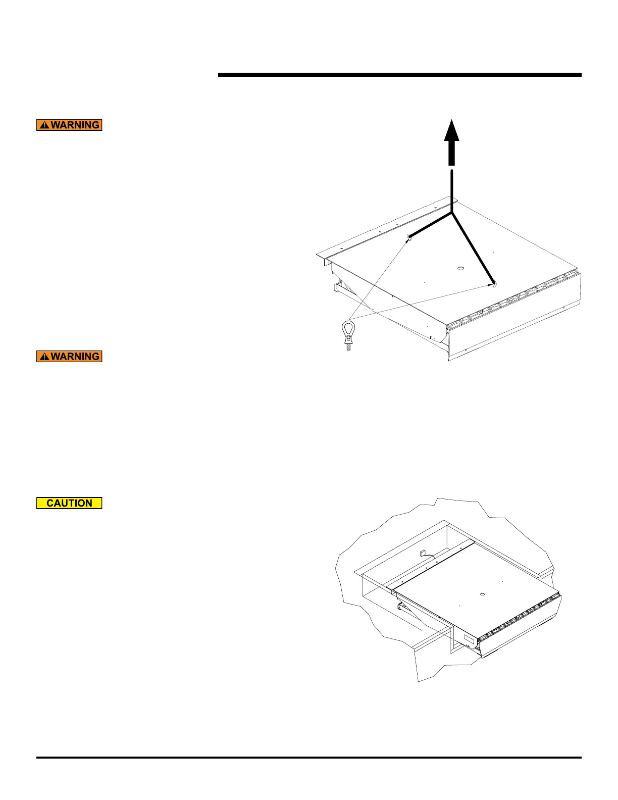
1. Prior to lifting leveler make sure the shipping tie down
bolts seen in Fig. 14 are in place. Install two 3/4”-10UNC
load centering eye bolts into the front and rear of the top
plate and hoist leveler into pit. The dock leveler should
not be lifted in any other manner when place into the pit.
See Fig. 4.
Inadequate lifting equipment or practices can cause a
load to fall unexpectedly. Make sure the lifting chain or
other lifting devices are in good condition and have a
rated capacity of at least 3500 lbs for the lifting angle
used. Never allow anyone to stand on or near the dock
leveler when it is lifted or placed into the pit. Stand clear
of the dock leveler when it is placed into the pit. Failure
to follow this warning can allow the dock leveler to fall,
tip, or swing into people, resulting in death or serious
injury.
Route power cord clear of edges and resting surfaces
so that it is not damaged during lifting and placement.
Plug end may be routed up through the rear hinge until
needed.
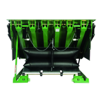
INSERTING THE LEVELER INTO THE PIT
2. Position dock leveler in pit about 7" away from the
rear pit wall. Connect cord from motor, and plugs from
switches to junction box at rear pit wall. Place the free
length of cord inside of frame area, free of interference
and wiring diagrams on page 15-24.
Fig. 4
3/4" - 10 UNC
load centering
eyebolt
Fig. 5