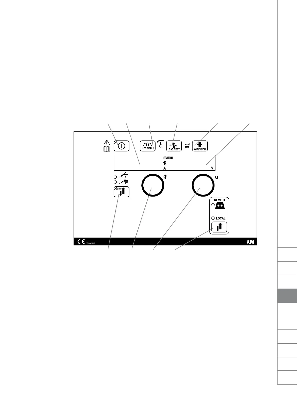
3.2 FRONT PANEL INDICATORS
Thefollowingindicatorscanbefoundonthefrontpanelofthedevice:
• Whenthegreenindicator,A3,ison,thepowersourceisinstandbymode.Thisindicator
isonwhenthemachineisconnectedtothemainssupplywiththemainswitchinthe‘I’
position.
• Whentheyellowoverheatingindicator(A4)ison,themachinehasoverheated.Thefan
then starts. When the indicator turns o, the machine can be used again.
• WhenindicatorA4blinks,themachinehasexperiencedafailure.Attempttoremedythe
problemaccordingtotheinstructionsinSection4,‘Troubleshooting’.Ifthefailurecannot
be eliminated, turn o the machine, and turn it on again. If the failure persists, write down
any fault code that may be shown on the display and contact authorised Kemppi service
agent.
P1 P2
P9P7
P3 P4 P5
P10
P6
P8
3.3 USE OF THE CONTROL PANEL
The control panel is used for controlling and monitoring the operation of the power source
and the wire feeder. The buttons are used for adjusting functions. The displays and indicators
reecttheoperatingmodesofthemachine.
3.3.1 Starting of the control panel
• Whenyoustartthepowersourcewiththemainswitch(A2),thecontrolpanelremainsin
OFFmodeandthewirefeederisnotoperational.Thedisplayshowsthetext‘OFF’.
• WhenyoudepressthestartbuttonP1foratleastonesecond,thecontrolpanelstarts.The
unit is now ready for welding and enters the mode that was active before the power was
cut o.
• Youcanalsostartthecontrolpanelbyquicklypressingtheweldinggunswitchthree
times.
3.3.2 Displays
• Whenyouareadjustingthemachinesettings,thecontrolpaneldisplaysshowadjustable
operation parameters, their values, and the units of measure.
• Duringwelding,displayP2showstheweldingcurrentvaluethatiscurrentlyinuse,while
display P6 shows the welding voltage.
EN
9
FastMig KM 300, 400, 500 / © Kemppi Oy /0901
FI
SV
NO
DA
EN
DE
NL
FR
ES
PL
RU
 Loading...