3.3.12 Calibration of the wire feed speed
When factory settings are used, the wire feed speed can be adjusted to between 4 and 100
without a unit of measurement. Only the LED symbol indicates that wire feed speed is the
parameter to be set.
The unit of the wire feed speed (m/min) is shown once the wire feed speed of the device has
beencalibrated.Toprogrammaticallycalibratethewirefeedspeed:
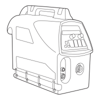
1. Topreparetheweldingequipmentforcalibrating,dothefollowing:
• Connectthewirefeedertothepowersourcewiththecontrolcable.
• Insertthellerwireinthegun,andrunthewireoutofthecontacttip.
• Adjustthefeederwheelssothattheyaresucientlytight.
• Startthepowersourceandturnonthecontrolpanelwiththestartbutton,P1.
2. Depress button P7 (SETUP) for at least ve seconds. The set-up menu appears on the
display.
3. Select the calibration menu (CAL) by rotating the left-hand knob, and then select the
value’Enter’(Ent)withtheright-handknob.AcceptyourselectionbypressingbuttonP10
(REMOTE/LOCAL)briey.
4. Usetheright-handknobtoselect‘m/min’asthevalueofmeasureforthequantitytobe
calibrated,andacceptyourselectionbybrieypressingbuttonP10(REMOTE/LOCAL).
5. Use the left-hand knob to set the rst calibration point to the desired value (e.g., 2.0 m/
min).
6. Cut the ller wire at the contact tip end. Press the trigger, and let the wire run until it stops
automatically.
7. Measure the length of the loose wire end to an accuracy of 1 cm.
8. Enter the measurement with the right-hand knob, and accept your selection by pressing
buttonP10(REMOTE/LOCAL)briey.
9. Use the left-hand knob to set the second calibration point to an appropriate value (e.g.,
18.0 m/min).
10. Repeat steps 6–8.
11. Themessage‘SuccES’appearsonthedisplaytoindicatethatcalibrationhasended
successfully.Atthesametime,thedeviceexitscalibrationmodeandreturnstobasic
operation mode.
4. TROUBLESHOOTING
In the event of a failure of the machine, contact an authorised Kemppi service agent. Before
taking your unit for servicing, check the list below.
4.1 OVERLOAD YELLOW INDICATOR LIT
Two simultaneously operating fans cool the power source. The machine may, however,
overheat if continuously loaded above the rated values or if the circulation of cooling air is
prevented.
Theyellowindicator(A10)islitintheeventofoverheating.Youthenneedtostopweldingand
let the machine cool down. The indicator light turns o when welding can be resumed.
4.2 CONTROL CABLE CONNECTOR FUSE
The rear wall of the power source contains fuse A9, which protects the control cable
connector, A7. Using an incorrect fuse may cause damage to the power source. It is important
thatyoualwaysusetherightkindoffuse.Thetypeandsizeofthefuseareindicatednextto
the fuse socket.
EN
12
FastMig KM 300, 400, 500 / © Kemppi Oy / 0901
FI
SV
NO
DA
EN
DE
NL
FR
ES
PL
RU

 Loading...

