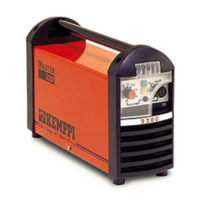
Control card A004 layout (Master / Mastertig 2800/3500)
X6
X5
X
1
X4
F1 1,6AT
R13
R1
R1 Power (Spark)
R13 Voltage (Spark)
IGBT gate pulses
Control card A001 functional testing
Control card power supply ?
(2 x 13 Vac)
Temperature watch PTC ?
Set value information ?
X2
X3
X1
X12
X13
X10
X11
R70
X17
X16
X15
X18
R48
R47
R98
R49
X8 X4X5
X14
X20
X2
X3
R53
X16
X15
X17
R75
R93R33
R72
X18
3
.
1
5
A
T
3
.
1
5
A
T
X1
X12
X13
X14
X10X11
X8 X4X5
Control card A001 develops the IGBT gate pulses. If the power supply part is OK, the
fuses are intact, the temperature watch PTCs are OK and correct set value info is received
from the potentiometer, then the gate pulses should be seen on connectors X10 and X11.
When the machine is idling, one must note that it is actually running intermittently.
27

 Loading...


