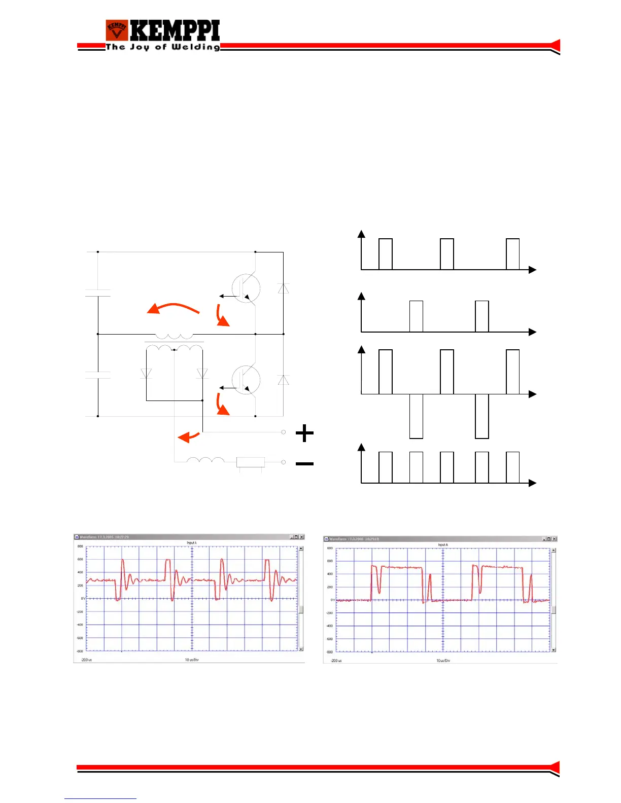
Operation principle
The power stage in Master- and Mastertig- power sources is a traditional half-bridge, where the
intermediate circuit´s dc-voltage is halved by load capacitors C2 and C3. IGBT-transistors are
used as power switches. When both IGBTs are not conductive, no power is transferred. When the
upper IGBT (V2) is conductive, there is positive voltage in the main transformer´s (T1) primary,
and when the lower IGBT (V3) is conductive there is negative voltage in the main transformer´s
(T1) primary.
Power is adjusted by altering the IGBT timings (PWM). The main transformer (T1) secondary
voltages are rectified by a full-wave rectifier.
U
G2
t
U
G3
t
U
1
t
U
2
t
C2
C3
V2
V3
T1
U
1
U
2
U
G2
U
G3
approx. + 320 V (1~) or approx. + 570 V (3~)
Voltage over the lower IGBT V3 with minimum power (3~)
Voltage over the lower IGBT V3 with maximum power (3~)
11
 Loading...