Composite Video
Signal
Display
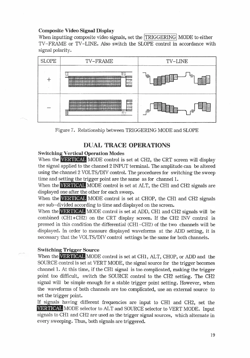
When
inputting composite video signals, set the
[TRIGGERING]
MODE
to either
TV-FRAME
or
TV-LINE.
Also
switch
the
SLOPE
control in accordance
with
signal
polarity.
Figure
7. Relationship between
TRIGGERING
MODE
and
SLOPE
DUAL
TRACE
OPERATIONS
Switching
Vertical
Operation Modes
When
the
iiiiigilMI
MODE
control is set at
CH2,
the
CRT
screen
will
display
the signal applied to the channel 2
INPUT
terminal. The amplitude can be altered
using
the channel 2
VOLTS/DIV
control. The procedures for switching the sweep
time and setting the trigger point are the same as for channel 1.
When
the
ESSI
MODE
control is set at
ALT,
the
CHI
and CH2 signals are
displayed
one after the
other
for each sweep.
When
the
BlaUBMl
MODE
control is set at
CHOP,
the
CHI
and CH2 signals
are sub-divided according to time and displayed on the screen.
When
the
MiaaWHW
MODE
control is set at
ADD,
CHI and CH2 signals
will
be
combined
(CH1+CH2)
on the CRT display screen. If the CH2 INV control is
pressed in this condition the differential
(CH1-CH2)
of the two channels
will
be
displayed.
In order to measure displayed waveforms at the ADD setting, it is
necessary
that
the
VOLTS/DIV
control settings be the same for both channels.
Switching Trigger Source
When
themaWMMWMODE control is set at
CHI,
ALT,
CHOP,
or
ADD
and the
SOURCE
control is set at
VERT
MODE,
the signal source for the trigger becomes
channel 1. At this time, if the
CHI
signal is too complicated, making the trigger
point too
difficult,
switch
the
SOURCE
control to the CH2 setting. The CH2
signal
will
be simple enough for a stable trigger point setting. However, when
the waveforms of both channels are too complicated, use an external source to
set the trigger point.
If
signals having different frequencies are input to CHI and CH2, set the
ES355SIMODE selector to
ALT
and
SOURCE
selector to
VERT
MODE.
Input
signals to
CHI
and CH2 are used as the trigger signal sources,
which
alternate in
every
sweeping.
Thus,
both signals are triggered.
19
SLOPE
TV-FRAME
TV-LINE

 Loading...


