OPERATING PROCEDURES
SINGLE
TRACE OPERATION
Alternating
Current
Display
With
the oscilloscope in the
initial
setting condition (refer to Section 5 of
CHECK-
ING
AND
ADJUSTMENT PRIOR
TO
MEASUREMENT),
display on the CRT
screen the signal applied to the CHI
INPUT
terminal. Adjust the signal ampli-
tude
to an easy to measure size by changing the
VOLTS/DIV
control setting. The
CHI
VARIABLE
control may be
rotated
to
change
the amplitude in continuous
fashion. However, if this is not necessary leave the setting at
CAL.
Next,
adjust the horizontal
SWEEP TIME/DIV
control to attain an easy to
measure display. Make sure to leave the
VARIABLE
control setting at
CAL.
Whenever the waveform begins to destabilize, it is necessary to use the triggering
operation. Rotating the trigger
LEVEL
control left or right
will
stabilize the wave-
form.
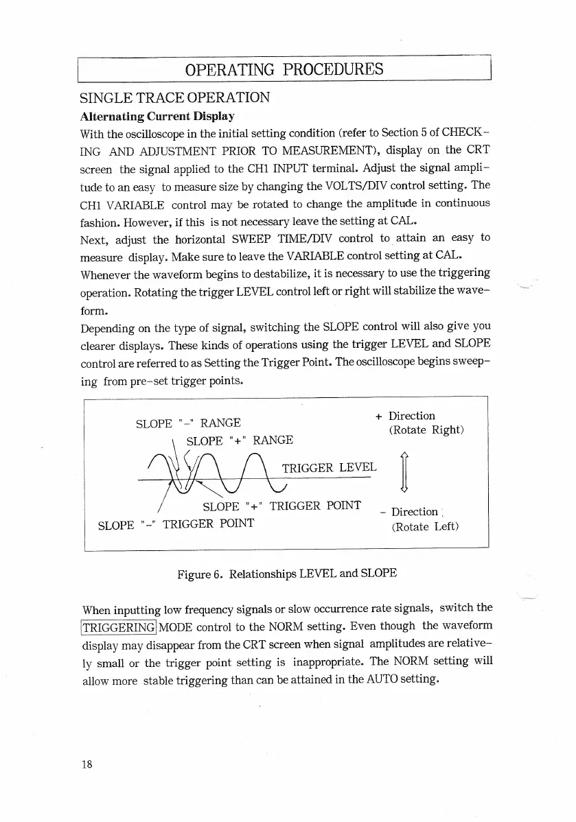
Depending on the type of signal, switching the
SLOPE
control
will
also give you
clearer displays. These kinds of
operations
using the trigger
LEVEL
and
SLOPE
control are referred to as Setting the Trigger Point. The oscilloscope begins sweep-
ing
from
pre-set
trigger points.
SLOPE
"
+
"
RANGE
When
inputting low frequency signals or slow occurrence
rate
signals, switch the
[TRIGGERING!
MODE
control to the
NORM
setting.
Even
though
the waveform
display may disappear from the
CRT
screen when signal amplitudes are relative-
ly
small or the trigger point setting is inappropriate. The
NORM
setting
will
allow
more stable triggering than can be attained in the
AUTO
setting.
18
TRIGGER
LEVEL
SLOPE
"
+
"
TRIGGER
POINT
SLOPE
"-"
TRIGGER
POINT
-
Direction;
(Rotate
Left)
SLOPE
"-"
RANGE
+
Direction
(Rotate Right)
Figure
6.
Relationships
LEVEL
and
SLOPE

 Loading...


