3.
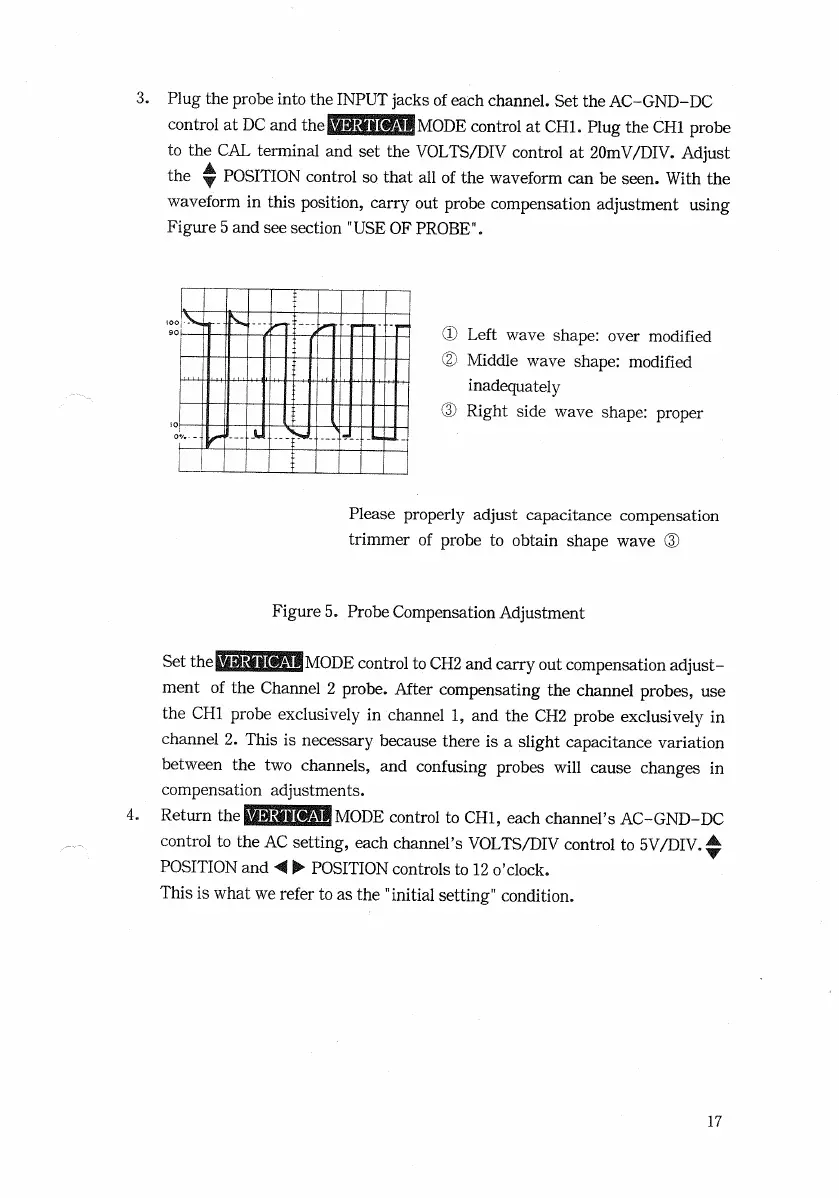
Plug the
probe
into the
INPUT
jacks of each channel. Set the
AC-GND-DC
control at
DC
and
thetfiWtWMllllMODE
control at
CHI.
Plug the
CHI
probe
to the
CAL
terminal and set the
VOLTS/DIV
control at
20mV/DIV.
Adjust
the y
POSITION
control so
that
all of the waveform can be seen.
With
the
waveform
in this position, carry out
probe
compensation adjustment using
Figure
5 and see section
"USE
OF
PROBE".
® Left
wave shape: over modified
®
Middle wave shape: modified
inadequately
(D Right side wave shape:
proper
Please properly adjust capacitance compensation
trimmer of
probe
to obtain
shape
wave ©
Figure
5. Probe Compensation Adjustment
Set
the
BPirilOH^ni
MODE
control to
CH2
and carry out compensation adjust-
ment of the Channel 2
probe.
After
compensating the channel probes, use
the CHI
probe
exclusively
in channel 1, and the CH2
probe
exclusively
in
channel 2.
This
is necessary because
there
is a slight capacitance variation
between the two channels, and confusing
probes
will
cause changes in
compensation adjustments.
4.
Return the
VMMMMMODE
control to
CHI,
each channel's
AC-GND-DC
control to the AC setting, each channel's
VOLTS/DIV
control to
5V/DIV.
^
POSITION
and < •
POSITION
controls to 12 o'clock.
This
is what we refer to as the
"initial
setting" condition.
17

 Loading...


