APPLICATIONS
Because
both the
vertical
and horizontal
axis
of the oscilloscope are calibrated,
the oscilloscope is capable of not only
displaying
waveforms but can also quantita-
tively
measuring voltage or time. When performing these latter measurements,
rotate
the three
VARIABLE
controls
(CHI [Y-axis],
CH2
[X-axis]
and horizon-
tal)
all the way in the
clockwise
direction to the
CAL
setting. All the
oscillo-
scope's
VARIABLE
controls
will
click
when rotated into their
CAL
settings.
In
addition, the oscilloscope comes
with
probes. These probes should all be
plugged into their proper
jacks
in order to assure a minimum of interference to
the signals you want to measure.
Measuring
Voltage Between Two Points on a Waveform
Use
the
following
procedures for measuring voltage, etc. between two points or
from
peak to peak on a waveform.
1.
Apply
a signal to the
INPUT
terminal and adjust the
VOLTS/DIV
and
SWEEP
TIME/DIV
controls.
Also
reset the trigger point if necessary. Set
the
AC-GND-DC
control at
AC.
2.
Work
the ^
POSITION
control so that one of the points (A) to be
measured
falls
on one of the horizontal graduation
lines,
while
the other
points
(B)
can
still
be observed on the
CRT
screen.
3.
Work
the 4\ •
POSITION
control so that point B
falls
on the
vertical
scale
at the center of the
CRT
screen.
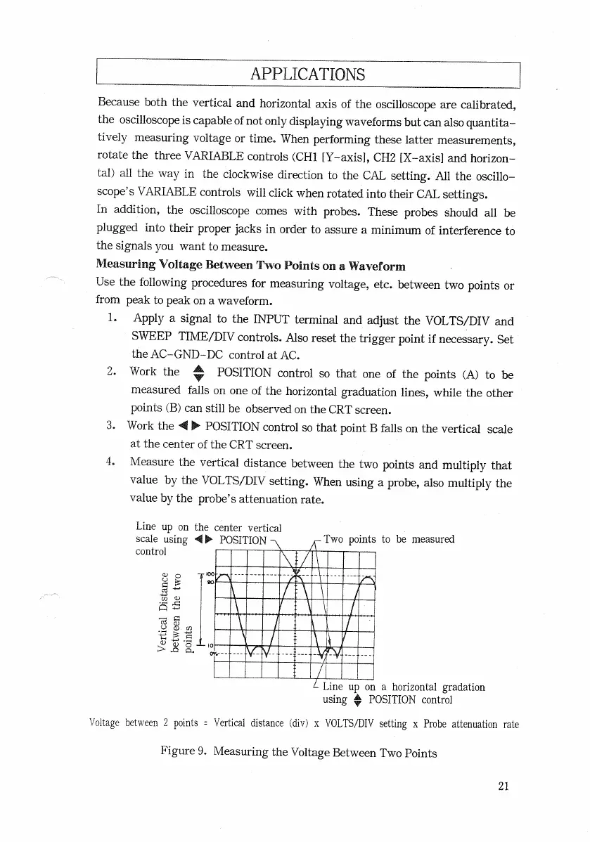
4. Measure the
vertical
distance between the two points and multiply that
value
by the
VOLTS/DIV
setting. When using a probe, also multiply the
value
by the probe's attenuation rate.
Voltage
between 2 points =
Vertical
distance (div) x
VOLTS/DIV
setting x Probe attenuation rate
21
Line
up on the center
vertical
scale
using At-
POSITION
control
Two
points to be measured
Vertical
Distance
between the two
points
Line
up on a horizontal gradation
using
*
POSITION
control
Figure
9. Measuring the Voltage Between Two Points

 Loading...


