CONNECTING INSTRUCTIONS
If
an additional turntable is used in order
to
operate
two
turntables, connect
the
left
channel
to
the
"L"
PHONO 2 input jack,
and the right channel
to
the
"R"
PH
ONO 2
input
jack.
If
the turntable has a grounding wire, connect
it
to this receiver's
GND terminal to avoid hum.
TAPE
DECK
CONNECTION
Recording
A tape deck can be connected for recording
as
follows. Left
channel input
of
the tape deck
to
TAPE A
"L"
REC
jack. Right channel
input
of
the tape deck
to
TAPE A
uR"
REC
jack.
Playback
A tape deck can be connected for playback
as
follows. Left
channel
output
of
the tape deck to TAPE A
"L"
PLAY jack. Right
channel
output
of
the tape deck to TAPE A
"R"
PLAY jack.
DIN
CONNECTOR
(REC/PLAY
CONNECTOR)
If
your tape deck is equipped
with
a DIN connector, connect it
to
the REC/PLAY connector
with
a DIN connecting cord. A DIN con-
nector enables recording and playback
with
this single cord.
NOTE:
When
a DIN cord is used for connecting
to
the tape deck. the PLAY and
REC
jacks should
not
be
used.
AUX
(AUXILIARY
INPUTS)
High level
AUX
input
jacks are for miscellaneous sources, such
as extra tape decks, additional tuners. TV sound outputs, and
other
ex-
ternal components.
FM
DET
OUT
JACK
The FM
detector
circuit
output
is made available here so
that
this
receiver
will
be ready for 4-channel broadcasting developments in the
future. When FM discrete 4-channel broadcasting becomes a reality.
a
simple
demodulator
connected here
will
enable you to fully enjoy this
coming development.
PRE
OUT
POWER
IN
If
a DOLBY N R adaptor is connected
to
the receiver "PRE OUT
POWER
IN"
jacks. not only can FM Dolby broadcasts be played back.
but
if
a tape deck
is
connected
to
the adaptor itself. Dolby system
recording and playback is possible. For
further
details refer
to
page
11.
MULTIPATH
JACKS
Those
who
have general oscilloscope
may
connect
it
and actually
see the incoming FM waveform. and turn the antenna
to
the setting
which
results in the least distorted waveform.
For detailed instructions on connections. etc
..
see the instruction ma-
nual supplied
with
the oscilloscope.
AC
OUTLET
The
AC
outlets
on the rear panel
of
the receiver may be used
to
supply
power
to
other components such
as
a turntable. tape deck. etc.
1.
SWITCH
ED
outlet
This
outlet
is controlled by the POWER
switch
on
the
front
panel.
(The capacity is
100
watts
maximum.)
2. UNSWITCHED outlets
These
outlets
are available at all times. (The
total
capacity is
300
watts
maximum.)
NOTE:
Units
shipped
to
the EUropean countries are
not
equipped
with
AC
OUTLETS.
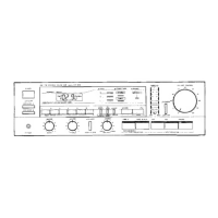
KR-9600
(K)
r
6
 Loading...