1-10 (No.RA094<Rev.002>)
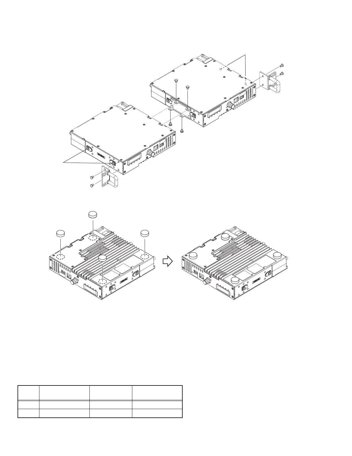
(3) Connect repeaters A and B with reinforcing HW and fix them with screws. <4>
(4) Attach two sets of brackets with handles to repeaters A and B. <5> <6>
2.3.3 Attaching the foot to the repeater
Remove the double-sided tape release paper of the foot, then attach the foot to the repeater.
2.4 MODIFICATION
2.4.1 Changing the AUX Port Configuration
The AUX Output Port (pins 14 and 18) on the CONTROL I/O (D-SUB 25-pin) connector is an open collector connection type as default,
and this port can absorb a maximum of 200 mA.
The AUX Output Port can be used as the output port for High (5 V pull-up resistor output) and Low by changing the configuration of
these pins.
Follow the procedure shown below to change the configuration.
(1) Remove the board.
(2) Remove the part from D558 and D560 on the board.
(3) Mount the resistor (part number: RK73GB2A473J) on R486 and R487 of the board respectively.
Signal
name
Connector
Pin Number
Removing
DA2J101
Installing
RK73GB2A473J
AO1 14 D558 R486
AO2 18 D560 R487
A
B
<4>
<4>
<5>
<6>
Screw hole
for rail mounting
M4 x 8 mm
Screw hole
for rail mounting
M4 x 8 mm
Note:
When mounting two repeaters in the rack,
it is recommended to use rails.
Use M4 x 8 mm screws for mounting the rails.
The length of the screw should not exceed 8 mm
to prevent damage inside the repeater.
Foot with double-sided tape
x4
 Loading...