NXR-700H
17
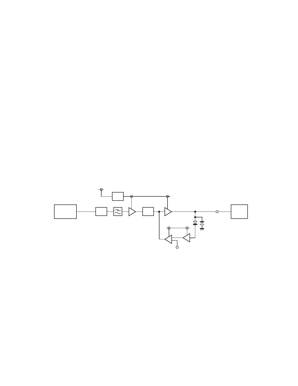
2-6. Driver circuit
The driver circuit amplifi es the transmitter frequency sig-
nal to the level required for input to the Final Unit (X45-385
A/5).
This circuit consists of RF amplifiers Q202 and Q203,
switches Q204, Q205 and Q206, and operating amplifier
IC201.
DC switches Q204, Q205, and Q206 turns the power
supply voltage of RF amplifi ers Q202, and Q203 on and off.
The output of the divide-by-2 IC (IC811) is attenuated by
attenuators R209, R210 and R211, by approximately 10dB.
So, the transmitter signal input level to Q202 is approxi-
mately –4dBm (0.4mW).
Q202 amplifi es it by approximately 15dB. So, the output
level is approximately +11dBm (12.6mW).
The output from Q202 is attenuated by attenuators R217,
R218 and R219, by approximately 3dB, and amplified by
Q203 approximately by 12dB. So, the output from Q203 is
approximately +20dBm (100mW). This output level is out-
put from the driver output connector CN802 and connected
to the Final Unit (X45-385 A/5).
Q203 has an AGC (Auto Gain Control) circuit. D201 recti-
fi es a part of the Q203 output and converts it into DC volt-
age. It is compared with the control voltage (D_PC) by the
operation amplifi er IC201. The Q203 Gate terminal voltage
is controlled for the stabilizing Q203 output (+20dBm).
Q202 Q203
TX main
PLL circuit
8V #1
Final
unit
D201
ATT
SW
ATT
146~
174MHz
D_PC
IC201
(A/2)
IC201
(B/2)
8V #1’
CN802
146~174MHz
+20dBm
8V #1’
Q204~206
Fig. 6 Driver circuit /
图 6 驱动电路
2-7. Modulation level adjustment circuit
The level adjustment circuit adjusts the modulation signal
level to provide the required level of modulation. This circuit
consists of IC301, IC304, IC305, and IC308.
The audio signal comes from the Control Unit (X53-413)
through pin 4. The modulating signal is input to IC304 from
this.
IC304 is an electronic volume control IC.
The modulation waveform balance adjustment, maximum
AF Dev. change, and adjustment are performed according to
data from the MPU using the FPU.
The modulation signal is produced by the modulating low-
pitched tone to the transmitter modulation 19.2MHz PLL cir-
cuit and adds the high-pitched modulation to the transmitter
main PLL.
IC305 is an inverting amplifi er (B/2) for inverting the am-
plification (A/2) of the modulating signal and synthesizing
CIRCUIT DESCRIPTION /
电路说明
2-6. 驱动电路
驱动电路将发射机频率信号放大到输入末级单元 (X45-385
A/5) 所需的电平。
该电路由RF 放大器Q202 和 Q203、 开 关 Q204、Q205 和
Q206 以及运算放大器 IC201 组成。
D C 开关 Q204、Q205 和 Q206 打开和关闭 RF 放大器 Q202 和
Q203 的电源电压。
二分频 IC(IC811) 的输出由衰减器 R209、R210 和 R211 衰
减约 10dB。因此,到 Q202 的发射机信号输入电平约为 -4dBm
(0.4mW)。
Q202 将其放大约15dB。因此,输出电平约为+11d B m
(12.6mW)。
Q202 的输出由衰减器 R217、R218 和 R219 衰减约 3d B,由
Q203 放大约 12d B。因此,Q203 的输出约为 +20d Bm(100mW)。
该输出电平从驱动器输出连接器 CN802 输出并连接到末级单
元 (X45-385 A/5)。
Q203 有一个 AGC( 自动增益控制 ) 电路。D201 对 Q203 的部
分输出进行整流,将其转换到 D C 电压。运算放大器 IC201 将
其与控制电压 (D_PC) 进行比较。对 Q203 栅极电压加以控制
以稳定 Q203 输出 (+20dBm)。
2-7. 调制电平调整电路
该电平调整电路调整调制信号电平,以提供所需的调制电
平。该电路由 IC301、IC304、IC305 和 IC308 组成。
音频信号经第 4 针来自控制单元 (X53-413)。调制信号由
此输入 IC304。
IC304 是一个电子音量控制 IC。
调制波形平衡调整、最大 AF Dev. 变化以及根据来自 M PU
的数据 ( 基于 FPU) 进行调整。
调制信号由到发射机调制 19.2MHz PLL 电路的调制低调音
和把高调调制加到发射机主 PLL 电路产生。
IC305 是一个反相放大器 (B/2),用于变换调制信号的放大
(A/2),合成 VCXO(X301) 控制电压和调制信号。

 Loading...