When the (¡)button in remote controller is pressed while the setting is displayed, the setting increases,
and a new setting is stored in RAM.
When the (1)button in remote controller is pressed while the setting is displayed, the setting increases,
and a new setting is stored in RAM.
When the (¡) or (1)button in remote controller is pressed continously, steps is change by 100ms period.
Step 1 Test mode STOP state [ t s m e ]
Step 2
Press the SKIP DOWN(4) button 5 times.
RESULT menu [ _ R S T U L T _ _ _ ]
Step 3 Press once the MD PLAY button. Indication of set value [ H A G : _ _ _ ]
Step 4
Press once the SKIP DOWN(4) button.
Indication of set value [ H B G : _ _ _ ]
Step 5
Press once the SKIP DOWN(4) button.
Indication of set value [ L A G : _ _ _ ]
Step 6
Press once the SKIP DOWN(4) button.
Indication of set value [ L B G : _ _ _ ]
Step 7
Press once the SKIP DOWN(4) button.
Indication of set value [ P E G : _ _ _ ]
Step 8
Press once the SKIP DOWN(4) button.
Indication of set value [ P F G : _ _ _ ]
Step 9
Press once the SKIP DOWN(4) button.
Indication of set value [ G E G : _ _ _ ]
Step 10
Press once the SKIP DOWN(4) button.
Indication of set value [ G F G : _ _ _ ]
Step 11
Press once the SKIP DOWN(4) button.
Indication of set value [ G C G : _ _ _ _ ]
Step 12 Press once the MD STOP button. RESULT menu state [ _ R E S U L T _ _ _ ]
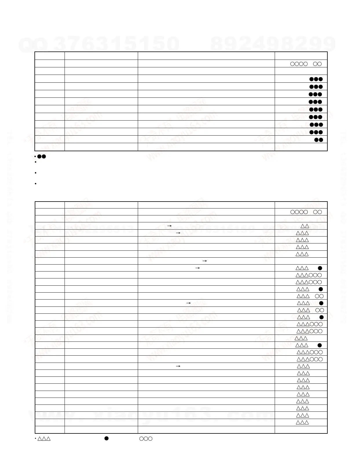
5. RESULT mode (final adjustment)
Step No.
Setting Method
Remarks Display
: Measurement value
Step 1 Test mode STOP state [ t s m e ]
Step 2
Press the SKIP DOWN(4) button 6 times.
MANUAL auxiliary adjustment mode [ _ M N U _ Y O B I _ ]
Step 3 Press once the MD PLAY button. Initial setting Temperature measuring mode [ T M P : _ _ _ _ ]
Step 4
Press once the SKIP DOWN(4) button.
Offset "0" setting A signal offset tentative measurement [ H A o : _ _ _ ]
Step 5
Press once the SKIP DOWN(4) button.
B signal offset tentative measurement [ H B o : _ _ _ ]
Step 6
Press once the SKIP DOWN(4) button.
E signal offset tentative measurement [ H E o : _ _ _ ]
Step 7
Press once the SKIP DOWN(4) button.
F signal offset tentative measurement [ H F o : _ _ _ ]
Step 8
Press once the SKIP DOWN(4) button.
Offset tentative measurement Laser ON [ L O N : _ _ _ _ _ _ ]
Step 9
Press once the SKIP DOWN(4) button.
Innermost periphery move RF side FG rough adjustment [ R F g : _ _ ]
Step 10
Press once the SKIP DOWN(4) button.
Focus ATT (A signal) tentative setting [ S A g : ]
Step 11
Press once the SKIP DOWN(4) button.
Focus ATT (B signal) tentative setting [ S B g : ]
Step 12
Press once the SKIP DOWN(4) button.
RF side pit section TG adjustment [ P T G : _ _ ]
Step 13
Press once the SKIP DOWN(4) button.
Pit section COUT level setting [ P C H : _ ]
Step 14
Press once the SKIP DOWN(4) button.
Outer periphery move RF side groove TG adjustment [ G T G : _ _ ]
Step 15
Press once the SKIP DOWN(4) button.
Groove section COUT level setting [ G C H : _ ]
Step 16
Press once the SKIP DOWN(4) button.
RF side TCRS adjustment [ R C G : _ _ ]
Step 17
Press once the SKIP DOWN(4) button.
Tracking ATT (E signal) setting [ S E G : ]
Step 18
Press once the SKIP DOWN(4) button.
Tracking ATT (F signal) setting [ S F G : ]
Step 19
Press once the SKIP DOWN(4) button.
Indication of tracking EFMIO measurement [ g M I : _ _ _ ]
Step 20
Press once the SKIP DOWN(4) button.
RF side pit section FG adjustment [R F G : _ _ ]
Step 21
Press once the SKIP DOWN(4) button.
Focus ATT (A signal) setting [ S A G : ]
Step 22
Press once the SKIP DOWN(4) button.
Focus ATT (B signal) setting [ S B G : ]
Step 23
Press once the SKIP DOWN(4) button.
Offset "0" setting A signal offset measurement [ H A O : _ _ _ ]
Step 24
Press once the SKIP DOWN(4) button.
B signal offset measurement [ H B O : _ _ _ ]
Step 25
Press once the SKIP DOWN(4) button.
E signal offset measurement [ H E O : _ _ _ ]
Step 26
Press once the SKIP DOWN(4) button.
F signal offset measurement [ H F O : _ _ _ ]
Step 27
Press once the SKIP DOWN(4) button.
TCRS signal offset measurement [ T C O : _ _ _ ]
Step 28
Press once the SKIP DOWN(4) button.
A signal offset measurement [ L A O : _ _ _ ]
Step 29
Press once the SKIP DOWN(4) button.
B signal offset measurement [ L B O : _ _ _ ]
Step 30
Press once the SKIP DOWN(4) button.
E signal offset measurement [ L E O : _ _ _ ]
Step 31
Press once the SKIP DOWN(4) button.
F
Step 32 Press once the MD STOP button. MNU YOBI state
signal offset measurement [ L F O : _ _ _ ]
[_MNU_YOBI_]
6. MANUAL auxiliary adjustment mode (only low reflection disc)
Step No.
Setting Method
Remarks Display
: Measurement value, : Set value, : Account value
 Loading...