TK-3170
41
ADJUSTMENT
Test Equipment Required for Alignment
Test Equipment Major Specifications
1. Standard Signal Generator Frequency Range 400 to 520MHz
(SSG) Modulation Frequency modulation and external modulation
Output –127dBm/0.1µV to greater than –47dBm/1mV
2. Power Meter Input Impedance 50Ω
Operation Frequency 400 to 520MHz or more
Measurement Capability Vicinity of 10W
3. Deviation Meter Frequency Range 400 to 520MHz
4. Digital Volt Meter Measuring Range 10mV to 10V DC
(DVM) Input Impedance High input impedance for minimum circuit loading
5. Oscilloscope DC through 30MHz
6. High Sensitivity Frequency Range 10Hz to 1000MHz
Frequency Counter Frequency Stability 0.2ppm or less
7. Ammeter 5A
8. AF Volt Meter Frequency Range 50Hz to 10kHz
(AF VTVM) Voltage Range 1mV to 10V
9. Audio Generator (AG) Frequency Range 50Hz to 5kHz or more
Output 0 to 1V
10. Distortion Meter Capability 3% or less at 1kHz
Input Level 50mV to 10Vrms
11. 4Ω Dummy Load Approx. 4Ω, 3W
12. Regulated Power Supply 5V to 10V, approx. 5A
Useful if ammeter equipped
■ Antenna Connector Adapter
The antenna connector of this radio uses an SMA termi-
nal. Use an antenna connector adapter [SMA(f) – BNC(f) or
SMA(f) – N(f)] for adjustment. (The adapter is not provided as
an option, so buy a commercially-available one.)
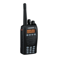
■ Battery Jig (W05-0909-00)
Connect the power cable properly between the battery jig
installed in the transceiver and the power supply, and be sure
output voltage and the power supply polarity prior to switch-
ing the power supply ON, otherwise over voltage and reverse
connection may damage the transceiver, or the power supply
or both.
When using the battery jig in user mode, the transceiver
assumes that a lithium-ion battery pack is attached to the
transceiver. In adjustment mode, battery type detection is
not performed. Refer to page 22 for details.
Note : When using the battery jig, you must measure the
voltage at the terminals of the battery jig. Otherwise, a slight
voltage drop may occur within the power cable, between the
power supply and the battery jig, especially while the trans-
ceiver transmits.
+ Terminal (Red)
– Terminal (Black)
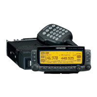
■ Nut wrench
In order to turn the volume nut and the channel selector
nut, use a recommendation tool.
KENWOOD part No. : W05-1123-00
S
–
+
C1
100P/25V
C2
470P/25V
C3
100/25V
R1
1.8M
+
+Terminal
(Red)
–Terminal
(Black)
Power
supply
Power
cable
Schematic diagram