504
227
224
503
505
215
309
306
308
204
211
214
206
205
223
110
114
113
121
118
131
127
124
120
119
117
104
106
203
106
107
105
112
228
229
304
116
115
219
401
218
307
506
217
111
108
326
135
325
302
324
313
507
231
320
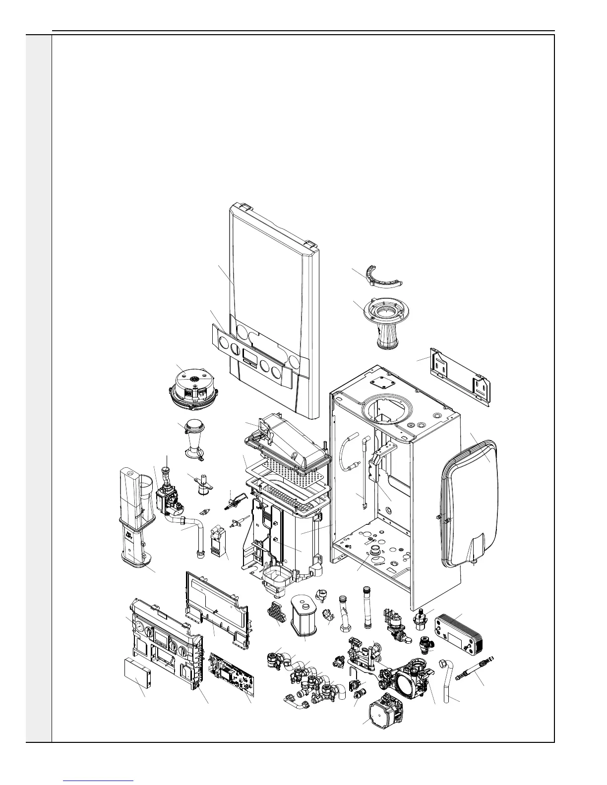
INSTALLATION
2.1 BOILER ASSEMBLY - EXPLODED VIEW
104 CH Return Valve
105 CH Flow Valve
106 DHW Inlet & Outlet
107 Filling Loop Pipe
108 Pump Head
110 Auto Air Vent
111 Divertor Valve Motor
112
Divertor Valve Body & Paddle
113 Pressure Relief Valve
114 Pipe - PRV Outlet
115 Pipe - Flow
116 Pipe - Return
117 Pipe - Expansion Vessel
118 Expansion Vessel
119 Return Group Manifold
120 Flow Group Manifold
121 Plate Heat Exchanger
124 Flow Regulator
127 Flow Sensor/Turbine
131 Water Pressure Switch
135 Pressure Gauge
203 Gas Cock
204 Pipe - Gas Inlet
205 Gas Valve
206 Pipe - Gas Injector
211 Injector Assy
214 Venturi
215 Fan
217 Burner
218 Gasket - Burner
219 Sump Clean Out Cover
223 Flue Manifold
224 Flue Manifold Top
227 Clamp Retaining Flue Turret
228 Hose Condensate Internal
229 Siphon Trap
231
Condensate Outlet Connection
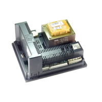
302 PCB
304
Control Thermistor (Return)
306 Electrode Ignition
307 Electrode Detection
308 Ignitor Unit
309 Thermistor Flow
313 Ignition Lead
320 Detection Lead
324 Control Box Lid
325 Control Box Front
326 Programmer Insert
401 Heat Engine
503 Wall Mounting Bracket
504 Front Panel
505 Fascia
506 Bracket - Gas Valve
507 Bracket - Expansion Vessel