Kit Contents
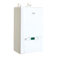
A. Outside Air Sensor
2.21 THE WEATHER COMPENSATION KIT - SUPPLIED AS STANDARD
This kit provides the facility to apply outside air temperature control to the boiler water
ow temperature which provides energy savings. The outside sensor provided measures
outside air temperature and sends a signal to the boiler, which adjusts the maximum boiler
ow temperature in response. If outside air temperature is greater than the system design
temperature, the boiler ow temperature is reduced providing running cost savings. The boiler
will operate in the condensing mode more frequently increasing savings.
Once the sensor is tted it is automatically detected.
The sensor operation may be congured by adjustment of the boiler operating parameters, if
necessary.
FITTING THE KIT
Note. A timer should be tted to the system so that CH will be switched off when appropriate.
Fitting the sensor
The air sensor should be located on an external wall of the building to be heated. Fix the
sensor to a north/north-east facing wall to avoid direct radiation from the sun. The air sensor
should be located to avoid any heating effect from the boiler ue.
To x the air sensor to the wall, unscrew the sensor box plastic cover and screw/plug the
sensor body to the wall.
Wire a twin core 0.5mm
2
cable from the sensor to the boiler through an RH grommet located
on the underside of the boiler. Cable length between sensor and boiler should be no greater
than 20m. Note that this connection is safety extra low voltage. It is not necessary for the
person carrying out the wiring to be approved to Part P of the Building Regulations.
Avoid running this cable alongside mains voltage cables.
Wiring the Weather Compensation Kit to the Keston Combi.
1. Isolate the electricity supply to the boiler.
2. Remove the boiler front panel (refer to boiler installation instructions).
3.
Swing the control box down into the service position, unclip and swing back the installer wiring
cover to latch into the retaining clips. Refer to Section 3.8.
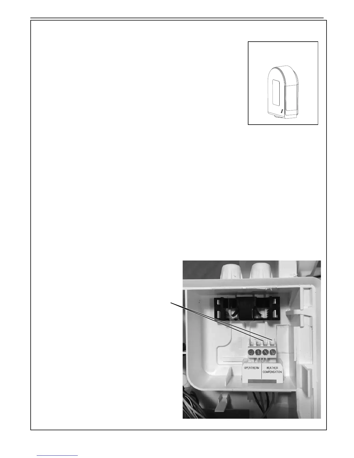
4. Connect the sensor wiring into the RHS of the 4 way terminal block and secure with the
strain relief .
5. Re-assemble in reverse order.
INSTALLER CONNECTIONS (RHS)
Note. If tting this with the boiler, then plese complete
product Fische system label, adding % efciency. This is
a Class II Control (2%).