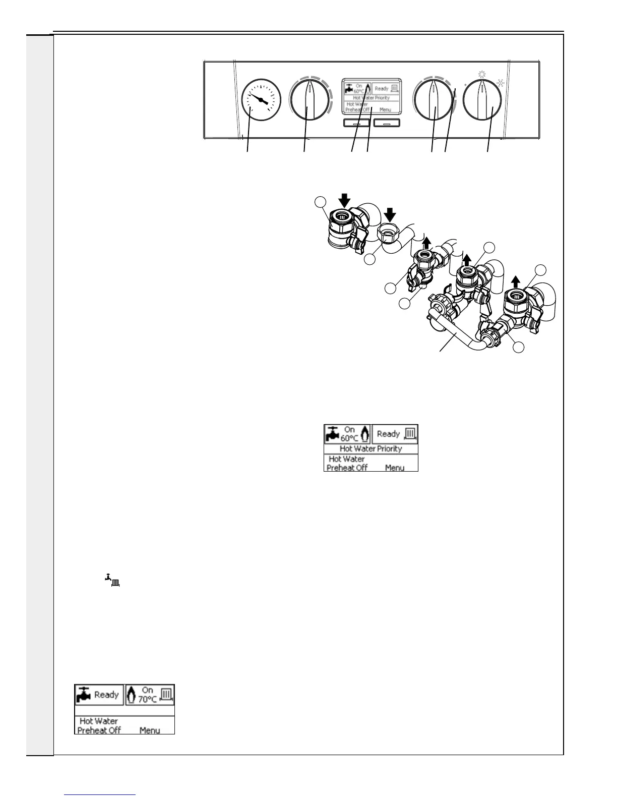
Legend
A. Domestic Hot Water Temperature Knob
B. Central Heating Temperature Knob
C. Mode Knob
D. Boiler Status Display
E. Burner ‘on’ Indicator
F. Central Heating Economy Setting
G. CH Flow Isolating Valve
H. Gas Inlet Pressure Test Point
I. Gas Service Cock
J. DHW Inlet Valve
K. CH Return Isolating Valve
L. DHW Outlet
M. Filling Loop Valve
N. Pressure Gauge
INSTALLATION
2.24 INITIAL LIGHTING
1. Check that the system has been lled and that the boiler is
not airlocked. Ensure the automatic air vent cap is open.
Note.
It is important the burner is not operated before the system is
fully vented of air. Refer to Vent System section page 38. If it
is necessary to operate the appliance pump to assist venting of
the air this must be done with the gas service cock turned off.
2. Ret the boiler front panel. Refer to Section 3.2.
3. Check that the drain cock is closed and that the CH and DHW
isolating valves (G,K & J) are OPEN.
4. Check that the electrical supply is OFF.
5. Check that the boiler mode knob (C) is OFF.
6. Check that the gas service cock (I) is OPEN.
7. Slacken the screw in the inlet pressure test point (H) and
connect a gas pressure gauge via a exible tube.
8. Switch the electricity supply ON and check all external controls
are calling for heat.
CENTRAL HEATING
9. Set the CH temp control (B) to max and turn the mode knob
(C) to ‘
’. The boiler control should now go through its
ignition sequence until the burner is established.
10. If the boiler does not light then after 5 attempts the boiler will
lock out and display “Ignition Lockout”.
Restart the boiler (Refer to Section 2.27). The boiler will
repeat its ignition sequence. If restart occurs 5 times within
15 minutes then “Too Many Restarts” will be shown.
When the burner is established a screen similar to the
following will be shown.
DOMESTIC HOT WATER
11. With the boiler ring, set the DHW Temp Knob (A) to
maximum and fully open a DHW tap.
The boiler should continue to run and the display should
change from showing
12. Ensure that with the boiler operating the dynamic gas
pressure is able to obtain maximum output. Refer to Table
2.
IMPORTANT
The gas input to the burner is regulated by the gas valve
according to the air ow produced by the fan. It is NOT
user-adjustable. Any interference to sealed settings on
the gas valve will adversely affect operation and render
our warranty void.
For additional gas supply information refer to “Gas Supply” on
page 12.
13. Turn off the DHW tap.
14. Remove gas pressure guage, tighten inlet pressure test
point and check for gas tightness.