2.7 INSTALLING THE BOILER
Installation of the boiler is straightforward but consideration must be given to access to allow ue and air pipes to be pushed
through walls and ceilings. The order in which the components are installed will depend upon particular site conditions, but in
general it will be easiest and most accurate to install the boiler and then build up the ue outlet and air inlet pipes to the terminal -
this is the sequence described.
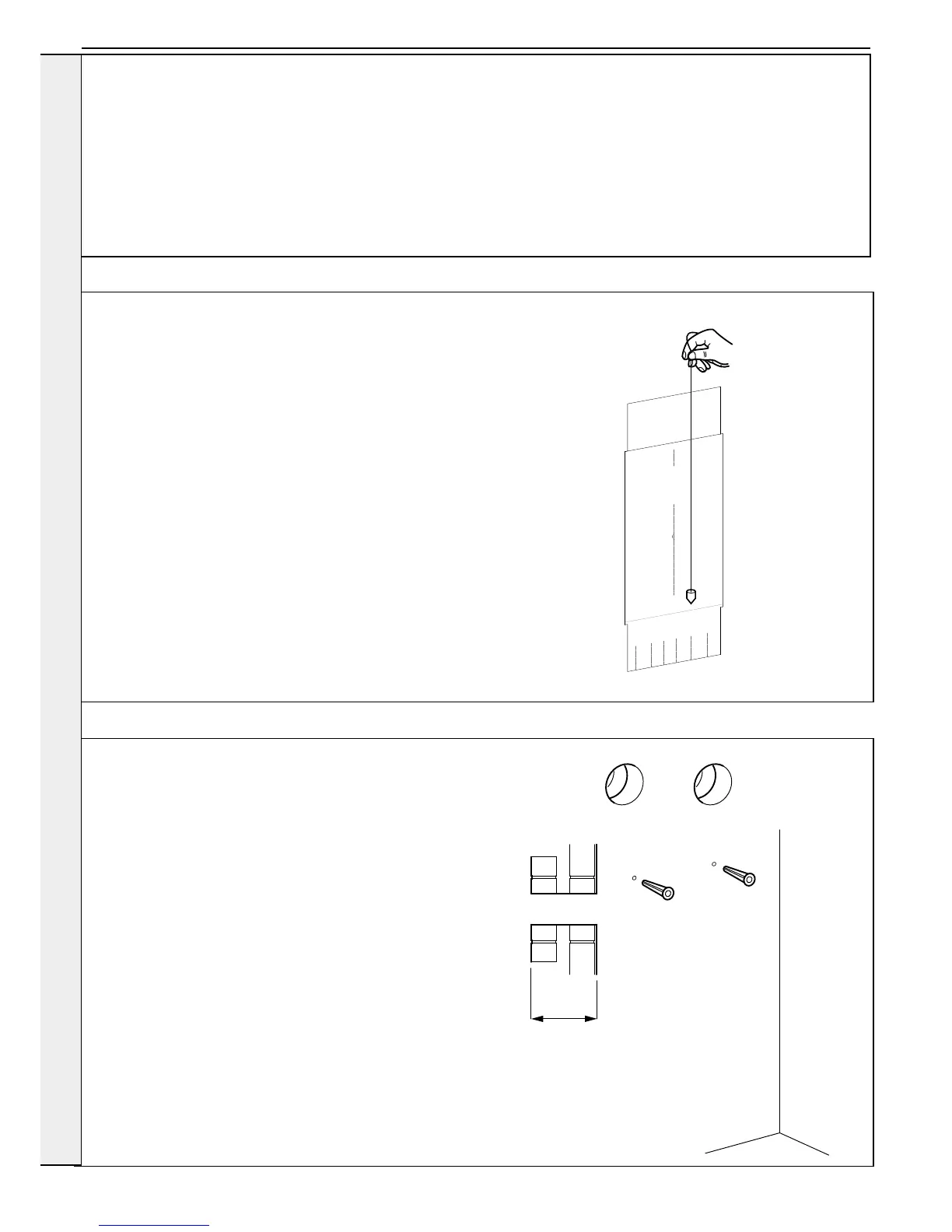
2.8 WALL MOUNTING TEMPLATE
The wall mounting template is located on the internal protective packaging.
Note.
The template shows the positions of the xing holes and the position of the air and
ue connections. Care MUST be taken to ensure the correct holes are drilled.
1. Tape template into the selected position. Ensure squareness by hanging a
plumbline as shown.
2. Mark onto the wall the following:
a The wall mounting plate screw positions (choose one from each group).
b The position of the air and ue when exiting straight out of the wall where the
boiler is mounted.
Note. Mark the centre of the hole as well as the circumference.
3. Remove the template from the wall.
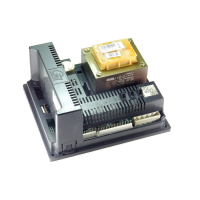
2.9 PREPARING THE WALL
IMPORTANT.
Ensure that, during the cutting operation, masonry falling outside of the
building does not cause damage or personal injury.
1. Cut the ue and air holes (preferably with 60mm core bore tool)
ensuring the holes are square to the wall.
2. Drill 2 holes with a 7.5mm / 8mm masonry drill and insert the plastic
plugs, provided, for the wall mounting plate.
3. Locate 2 No.14 x 50mm screws in the wall mounting plate (one at
each side, in any of the 3 holes provided at each side) and screw
home.
INSTALLATION