2.12 ASSEMBLY PRACTICE
Remove all plastic debris and burrs when installing air intake piping. Plastic llings caused by cutting muPVC pipe must not be
allowed to be drawn into the combustion air blower. Prevent dust entering the air intake when cutting on building sites. Blower failure
which is determined to be caused by plastic lings or other debris will not be covered by guarantee.
INSTALLING FLUE AND AIR PIPES
Important - When installing a replacement boiler a new ue
system is recommended. However re-using the existing boiler
ue installation is acceptable if the installer checks and conrms:
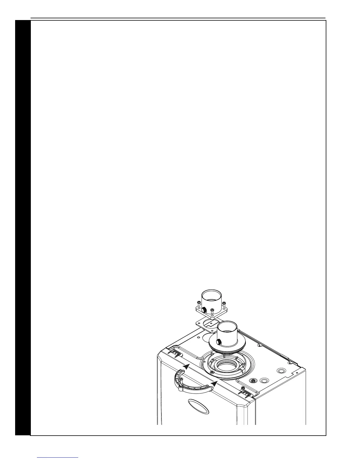
• Remove the ue adaptor and air spigot from the ue pack
supplied with the boiler.
• Remove boiler front panel - Section 3.2.
• Remove air intake blanking plate by unscrewing 4 x M5
screws and put to one side, leaving sponge gasket in
place.
• Fix air spigot to boiler using the 4 M5 screws, see diag.
below. Ensure sponge gasket is in place and not damaged.
• Ensure the condense trap/siphon is lled with water.
• Insert the ue adaptor into the ue manifold on the top of the
boiler and secure using the clamp provided in the packaging
box, see diagram below.
• Measure, cut and check the air and ue pipes to pass to the
exit from the wall(s) or ceiling.
• Always thoroughly deburr all pipes and most important,
remove shavings from within the pipe.
• Assemble, using solvent weld cement, the pipework from
the boiler connections to the exit from the rst wall/ceiling,
(remount the boiler if removed). When pushing pipe through
walls, ensure grit and dust is not allowed to enter the pipe.
Ensure pipes are fully engaged into sockets and solvent
welded with no leaks.
• Using the same methods drill any further holes (always
covering existing pipework), cut and assemble the pipework.
• From outside, complete the two terminations - See Section
2.3 Flue System and make good all holes. (Wall sealing
collars are available to make good hole areas on the wall
face (part number C.08.0.00.07.0).
• Support any pipes whose route could be displaced
either of its own accord or by accident. Any horizontal
run over 1m or vertical runs of any length must always
be supported. Brackets should be placed at intervals
of approximately 1m. Brackets should be loose enough
on the pipe to allow thermal expansion and contraction
movement.
• Flue pipework through walls MUST be sleeved to allow
thermal expansion and contraction movement.
• Check all connections for security and re-seal any joints
using solvent cement where soundness may be in doubt.
Note. It is equally important to seal the air inlet with solvent
cement as the ue outlet pipe joints.