FLUE SYSTEM........ CONT’D
TERMINATION OF THE FLUE AND AIR
The ue and air pipes may terminate independently through any
external walls within the same dwelling except on opposing walls,
within the maximum lengths shown in graph below. (Alternatively
a vertical ue pipe termination is acceptable.)
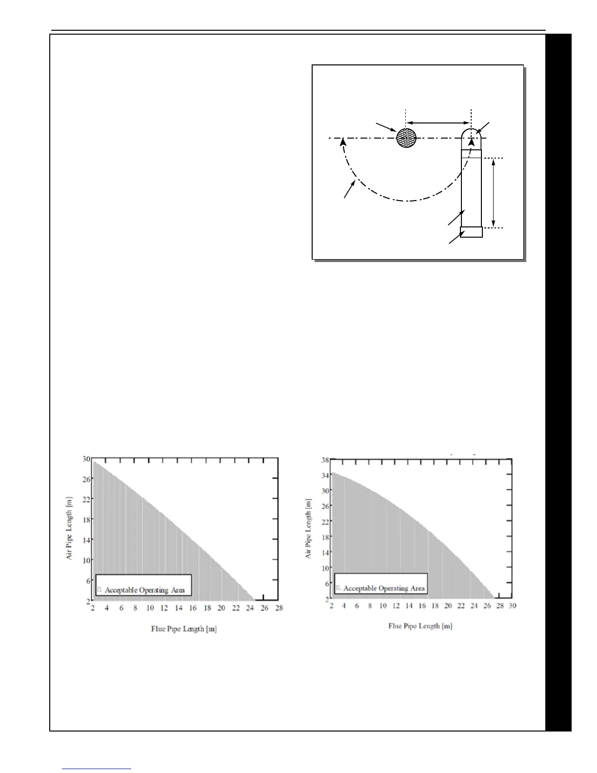
The air pipe must have an elbow and 150mm length of pipe
directed downwards with a termination grill tted.
The air pipe can be situated at the side or beneath the ue pipe to
a minimum dimension of 140mm (see diagram below). It must not
be sited above the ue pipe.
The ue and air pipes must extend by at least 40mm from the wall
surface.
Condensing boiler emit a visible plume of water vapour from the
ue terminal, this is normal. It is the responsibility of the installer
to judiciously select a terminal location that does not cause a
nuisance.
If either the ue or air terminal is below a height of 2m from
ground level a terminal guard must be tted.
Note. Any veritcal termination MUST have the terminals tted
and the air intake comply with the dimensions above.
MAXIMUM LENGTHS
Due to the resistance presented by extended ue length a slight reduction in maximum boiler output will occur where combined
ue and air lengths in excess of 18.0m and 16.0m (50mm muPVC) are used. In such cases the boiler output will be reduced by
0.6% and 0.8% per additional metre.
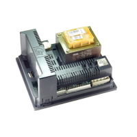
The maximum lengths of both air inlet pipe and ue outlet pipe, when no bends are used, are as detailed in graphs below.
However, each bend used has an equivalent length that must be deducted from the maximum straight length stated in graphs
below. Knuckle bends must not be tted.
A 92.5º swept elbow is equivalent to 1.0m straight length. A 45º bend is equivalent to 0.5m straight length.
It is possible to have variable ue and air lengths as described within the shaded area of graphs below.
SLOPE
‘Horizontal’ ue outlet pipework MUST slope at least 1.5 degrees (26mm per metre run) downwards towards the boiler.
Pipework can be vertical. Only swept elbows can be used.
Air inlet pipework can be truly horizontal or vertical, or sloping in a downward direction towards the boiler but in each case rain,
etc., must be prevented from entering the pipe. There must be no troughs in any of the pipework, whether it be air inlet or
ue outlet.
Keston Combi C35 - Flue & Air Pipe Length Keston Combi C30 - Flue & Air Pipe Length