21
EN
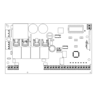
3 - PRELIMINARY CHECKS
2.4 - List of cables required
The cables required for connection of the various devices in a stan-
dard system are listed in the cables list table.
Before installing the product, perform the following checks and in-
spections:
check that the gate, the door or the barrier is suitable for automation;
the weight and size of the gate or door and the balance of the barrier
boom must be within the operating limits specied for the automa-
tion system in which the product is installed;
heck that the gate or door has rm, effective mechanical safety
stops;
make sure that the product xing zone is not subject to ooding;
high acidity or salinity or nearby heat sources might cause the pro-
duct to malfunction;
in case of extreme weather conditions (e.g. snow, ice, wide tempe-
rature variations or high temperatures), friction may increase, cau-
sing a corresponding rise in the force needed to operate the system;
the starting torque may therefore exceed that required in normal
conditions;
check that when operated by hand the gate, the door or the barrier
moves smoothly without any areas of greater friction or derailment
risk;
check that the gate, door or the barrier is well balanced and will the-
refore remain stationery when released in any position;
check that the electricity supply line to which the product is to be
connected is suitably earthed and protected by an overload and dif-
ferential safety breaker device;
he system power supply line must include a circuit breaker device
with a contact gap allowing complete disconnection in the condi-
tions specied by class III overvoltage;
ensure that all the material used for installation complies with the
relevant regulatory standards.
The cables used must be suitable for the type of installation; for
example, an H03VV-F type cable is recommended for indoor appli-
cations, while H07RN-F is suitable for outdoor applications.
- Power supply with protection against short-circuits inside the con-
trol unit, on motors and on the connected accessories;
- Obstacle detection;
- Automatic learning of working times;
- Safety device deactivation by means of dip switches: there is no
need to bridge the terminals of safety devices which are not instal-
led - the function is simply disabled by means of a dip switch.
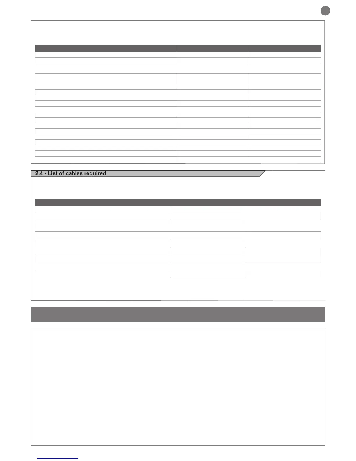
* If the power supply cable is more than 20 m long, it must be of larger gauge (3x2.5mm
2
) and a safety grounding system must be installed
near the automation unit
** Two cables of 2 x 0.5 mm
2
can be used as an alternative
ELECTRIC CABLE TECHNICAL SPECIFICATIONS
Connection cable maximum allowable limit
Control unit power supply line 1 x cable 3 x 1,5 mm
2
20 m *
Flashing light, courtesy light
Antenna
3 x 0,5 mm
2
**
1 x cable type RG58
20 m
20 m (advised < 5 m)
Electric lock 1 x cable 2 x 1 mm
2
10 m
Transmitter photocells 1 x cable 2 x 0,5 mm
2
20 m
Receiver photocells 1 x cable 4 x 0,5 mm
2
20 m
Sensitive edge 1 x cable 2 x 0,5 mm
2
20 m
Key-switch 1 x cable 4 x 0,5 mm
2
** 20 m
Motor power supply line 1 x cable 2 x 1,5 mm
2
10 m
TECHNICAL SPECIFICATIONS CT202 24 CT202 24L
Power supply (L-N) 230Vac (+10% - 15%) 50/60 Hz 115Vac (+10% - 15%) 50/60 Hz
Rated power maximum 210W maximum 210W
Photocell power supply output
24Vdc (without regulation)
maximum 250mA
24Vdc (without regulation)
maximum 250mA
Output for Vac accessories power/device test power Vdc
24 Vac without regulation 200 mA /
24 Vdc without regulation 250 mA
24 Vac without regulation 200 mA /
24 Vdc without regulation 250 mA
Flashing light output 24Vdc (without regulation) 15W 24Vdc (without regulation) 15W
Courtesy light output 24Vdc (without regulation) 15W 24Vdc (without regulation) 15W
Electric lock output 12Vac 15VA maximum 12Vac 15VA maximum
Gate open warning light output 24Vdc (without regulation) 5W 24Vdc (without regulation) 5W
Antenna input 50Ω type cable RG58 50Ω type cable RG58
Operating temperature -20°C + 55°C -20°C + 55°C
Accessory fuses 2AT 2AT
Power supply line fuses 1.6AT 3.15AT
Max. number of transmitters storage FIX CODE 150 150
Max. number of transmitters storage ROLLING CODE 150 150
Use in particularly acid, saline or explosive atmospheres NO NO
Protection class IP54 IP54
Control unit dimensions 222 x 110 x 275 H mm 222 x 110 x 275 H mm
Weight 3,93 kg 3,93 kg
 Loading...


