EasyManuals Logo

Key Automation CT202 24 User Manual

Key Automation CT202 24
Go to English
116 pages
To Next Page IconTo Next Page
To Previous Page IconTo Previous Page
Page #38 background imageLoading...
Page #38 background image
38
FR
4 - INSTALLATION DU PRODUIT
4.1 - Branchements électriques
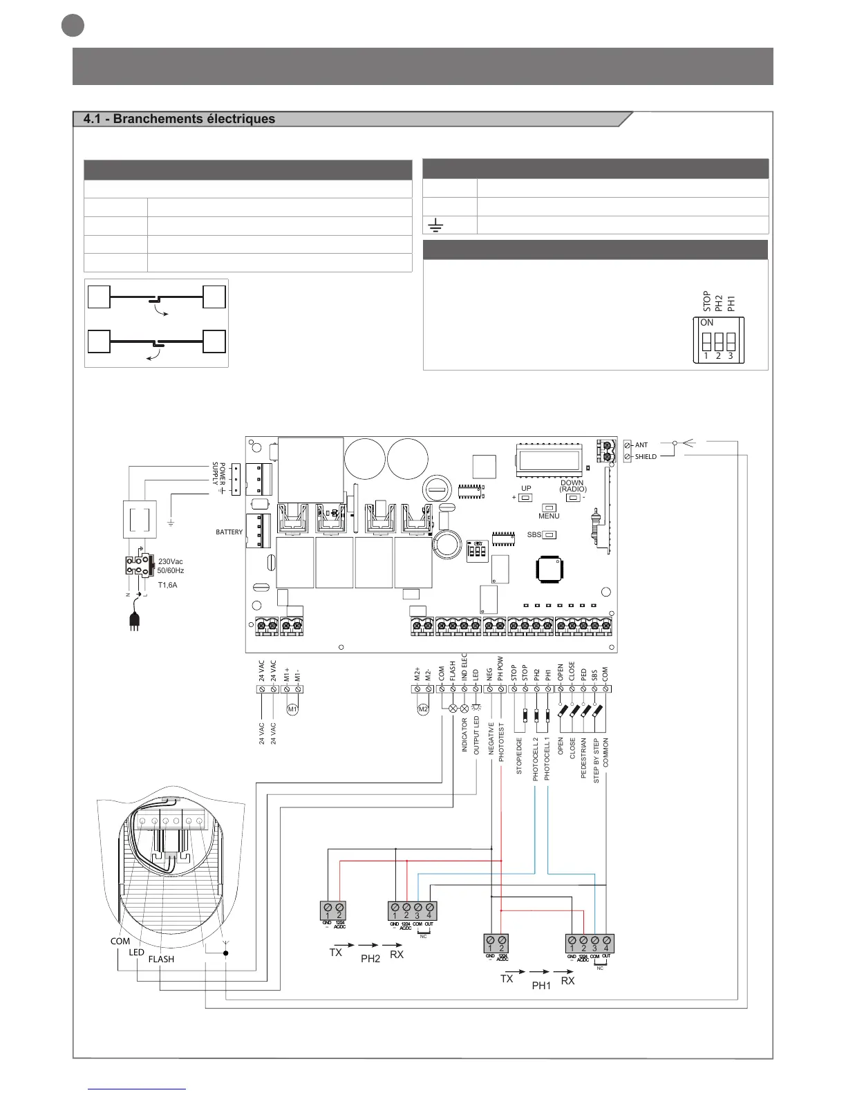
ATTENTION - Avant d’effectuer les branchements, vérier que la logique de commande n’est pas sous tension.
ON
1 2 3
STOP
PH2
PH1
BRANCHEMENT MOTEURS
Bornier des branchements d’alimentation
M1 + Alimentation moteur M1 +
M1 - Alimentation moteur M1 -
M2 + Alimentation moteur M2 +
M2 - Alimentation moteur M2 -
CONNECTEUR ALIMENTATIONS
L Phase alimentation 230 Vac (120 Vac) 50-60 Hz
N Neutre alimentation 230 Vac (120 Vac) 50-60 Hz
Terre
SÉLECTEUR COMMUTATEUR DIP
Sur ON, il désactive les entrées STOP, PH1, PH2
Évite de devoir shunter les entrées sur le bornier.
ATTENTION - avec le commutateur DIP
sur ON, les dispositifs de sécurité
raccordés sont exclus
PHOTOTEST
OUTPUT LED
OPEN
PHOTOCELL 1
PHOTOCELL 2
CLOSE
PEDESTRIAN
STEP BY STEP
COMMON
STOP/EDGE
INDICATOR
NEGATIVE
24 VAC
24 VAC
M1 M2
2
3
4
1
1
2
TX
RX
NC
PH2
2
3
4
1
1
2
TX
RX
PH1
GND
_
12/24
AC/DC
GND
_
12/24
AC/DC
COM
OUT
GND
_
12/24
AC/DC
GND
_
12/24
AC/DC
COM
OUT
NC
N
T1,6A
L
230Vac
50/60Hz
COM
LED
FLASH
24 VAC
24 VAC
M1+
M1-
M2+
M2-
COM
FLASH
IND ELEC
LED
NEG
PH POW
STOP
STOP
PH2
PH1
OPEN
CLOSE
SBS
PED
COM
BATTERY
SHIELD
ANT
POWER
SUPPLY
UP
+
-
MENU
SBS
DOWN
(RADIO)
M1M2
M2M1

Table of Contents

Questions and Answers:

Question and Answer IconNeed help?

Do you have a question about the Key Automation CT202 24 and is the answer not in the manual?

Key Automation CT202 24 Specifications

General IconGeneral
BrandKey Automation
ModelCT202 24
CategoryControl Unit
LanguageEnglish

Related product manuals