EasyManuals Logo

Key Automation CT202 24 User Manual

Key Automation CT202 24
Go to English
116 pages
To Next Page IconTo Next Page
To Previous Page IconTo Previous Page
Page #22 background imageLoading...
Page #22 background image
22
EN
4 - PRODUCT INSTALLATION
4.1 - Electrical connections
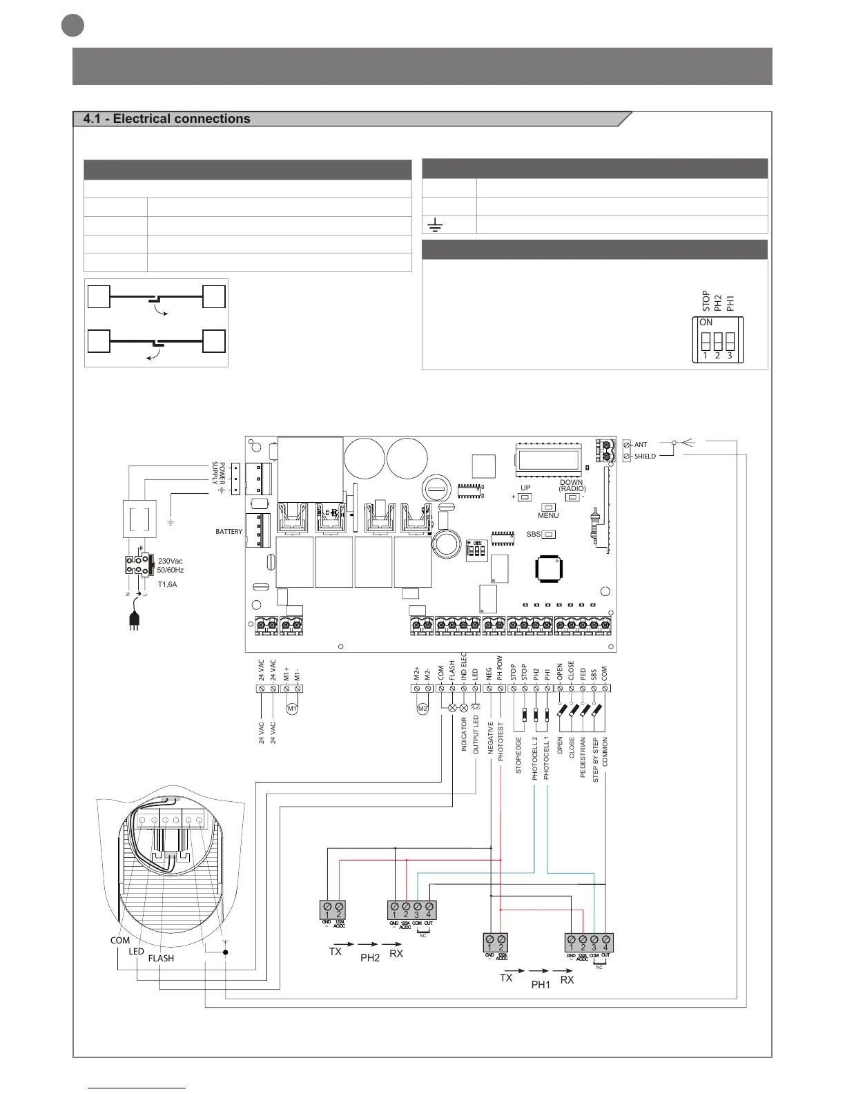
WARNING - Before making the connections, ensure that the control unit is not powered up.
ON
1 2 3
STOP
PH2
PH1
MOTOR CONNECTION
Power supply connection terminal board
M + Power supply of motor M1 +
M - Power supply of motor M1 -
M2 + Power supply of motor M2 +
M2 - Power supply of motor M2 -
POWER SUPPLY CONNECTOR
L Power supply live 230 Vac (120 Vac) 50-60 Hz
N Power supply neutral 230 Vac (120 Vac) 50-60 Hz
Earth
DIP SWITCH
Set on “ON” to disable inputs STOP, PH1, PH2
Eliminates the need to bridge the terminal board inputs.
WARNING - with the dip switch ON,
the safety devices are disabled
PHOTOTEST
OUTPUT LED
OPEN
PHOTOCELL 1
PHOTOCELL 2
CLOSE
PEDESTRIAN
STEP BY STEP
COMMON
STOP/EDGE
INDICATOR
NEGATIVE
24 VAC
24 VAC
M1 M2
2
3
4
1
1
2
TX
RX
NC
PH2
2
3
4
1
1
2
TX
RX
PH1
GND
_
12/24
AC/DC
GND
_
12/24
AC/DC
COM
OUT
GND
_
12/24
AC/DC
GND
_
12/24
AC/DC
COM
OUT
NC
N
T1,6A
L
230Vac
50/60Hz
COM
LED
FLASH
24 VAC
24 VAC
M1+
M1-
M2+
M2-
COM
FLASH
IND ELEC
LED
NEG
PH POW
STOP
STOP
PH2
PH1
OPEN
CLOSE
SBS
PED
COM
BATTERY
SHIELD
ANT
POWER
SUPPLY
UP
+
-
MENU
SBS
DOWN
(RADIO)
M1M2
M2M1

Table of Contents

Questions and Answers:

Question and Answer IconNeed help?

Do you have a question about the Key Automation CT202 24 and is the answer not in the manual?

Key Automation CT202 24 Specifications

General IconGeneral
BrandKey Automation
ModelCT202 24
CategoryControl Unit
LanguageEnglish

Related product manuals