EasyManuals Logo
Home>Key Automation>Control Unit>CT202 24

Key Automation CT202 24 User Manual

Key Automation CT202 24
Go to English
116 pages
To Next Page IconTo Next Page
To Previous Page IconTo Previous Page
Page #54 background imageLoading...
Page #54 background image
54
ES
4 - INSTALACIÓN DEL PRODUCTO
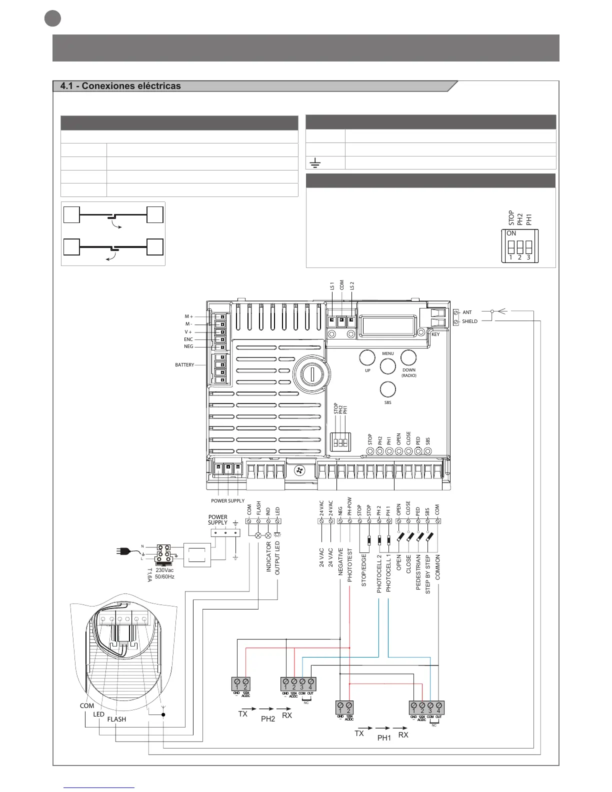
4.1 - Conexiones eléctricas
ATENCIÓN - Antes de realizar las conexiones, compruebe que la central no esté alimentada
NEG
PH-POW
STOP
STOP
PH 2
COM
FLASH
IND
LED
24 VAC
24 VAC
PH 1
OPEN
CLOSE
SBS
PED
COM
PHOTOTEST
OUTPUT LED
OPEN
PHOTOCELL 1
PHOTOCELL 2
CLOSE
PEDESTRIAN
STEP BY STEP
COMMON
STOP/EDGE
INDICATOR
NEGATIVE
24 VAC
24 VAC
2
3
4
1
1
2
TX
RX
NC
PH2
2
3
4
1
1
2
TX
RX
PH1
GND
_
12/24
AC/DC
GND
_
12/24
AC/DC
COM
OUT
GND
_
12/24
AC/DC
GND
_
12/24
AC/DC
COM
OUT
NC
POWER
POWER SUPPLY
SUPPLY
N
T1,6A
L
230Vac
50/60Hz
COM
LED
FLASH
STOP
STOP
PH2
PH1
OPEN
CLOSE
PED
SBS
PH2
PH1
SHIELD
UP
MENU
SBS
DOWN
(RADIO)
ANT
NEG
ENC
V +
M -
M +
BATTERY
LS 1
LS 2
KEY
COM
ON
1 2 3
STOP
PH2
PH1
CONEXIÓN DE LOS MOTORES
Regleta de conexiones alimentación
M1 + Alimentación del motor M1 +
M1 - Alimentación del motor M1 -
M2 + Alimentación del motor M2 +
M2 - Alimentación del motor M2 -
CONECTOR ALIMENTACIONES
L Fase alimentación 230 Vac (120 Vac) 50-60 Hz
N Neutro alimentación 230 Vac (120 Vac) 50-60 Hz
Tierra
SELECTOR DIP SWITCH
Ajustado en “ON” inhabilita las entradas STOP, PH1, PH2.
Elimina la necesidad de puentear las entradas en la regleta.
ATENCIÓN - con el dip switch en ON, los
dispositivos de seguridad conectados
quedan desactivados
M1M2
M2M1

Table of Contents

Questions and Answers:

Question and Answer IconNeed help?

Do you have a question about the Key Automation CT202 24 and is the answer not in the manual?

Key Automation CT202 24 Specifications

General IconGeneral
BrandKey Automation
ModelCT202 24
CategoryControl Unit
LanguageEnglish

Related product manuals