Home
Keysight Technologies
Measuring Instruments
N5222B
Keysight Technologies N5222B User Manual
4
of 1
of 1 rating
88 pages
Give review
Manual
Specs
To Next Page
To Next Page
To Previous Page
To Previous Page
Loading...
24
Installation Note N5222-90
131
Description of the Upgrade
Installation Procedur
e for the Upgrade
-
Step 11. R
emove the A70 LFE Boar
d Bracket
Remov
e the LFE br
acket as indicat
ed (it
em
➀
). Refer to
Figure 7
.
Figur
e 7
Remove the Screws (x4) and LFE Bracket (0515-037
2, N5240-00011)
23
25
Table of Contents
Description of the Upgrade
3
Getting Assistance from Keysight
4
Contacting Keysight
4
Getting Prepared
5
License Key Redemption
6
Verify the License Contents
6
Verify the Model/Version of HMA26.5 Installed
7
Downloading the Online PNA Service Guide
8
Protecting Your Workspace from Electrostatic Discharge
8
Tools Required for the Installation
9
About Installing the Upgrade
10
Items Included in the Upgrade Kit
11
Installation Procedure for the Upgrade
15
Overview of the Installation Procedure
15
Step 1. Obtain a Keyword and Verify the Information
17
Step 2. Remove the Outer Cover
18
Step 3. Remove the Inner Cover
18
Step 4. Remove the Front Panel Assembly
18
Step 5. Remove the A19 Test Set Motherboard
18
Step 6. Disconnect A71 and A74 Bias-Tee Combiner’s LFE Cables From the A70 Low Frequency Extension (LFE) Board and the Ends of the LFE Cables Connected to the IF Multiplier (IF MUX) Board
19
Step 7. Remove the A75 Low Frequency Extension (LFE) Board
20
Step 8. Remove Some Low Frequency Extension (LFE) Cables (8120-5014 (x1), 8120-5021 (x1), N5240-60097 (x1), and N5240-60098) From the IF Multiplexer (IF MUX) Board
21
Step 9. Remove Some of the Mixer Brick (MXB) Cables
22
Step 10. Remove Some Gray Cables From the A20 IF Multiplexer Board
23
Step 11. Remove the A70 LFE Board Bracket
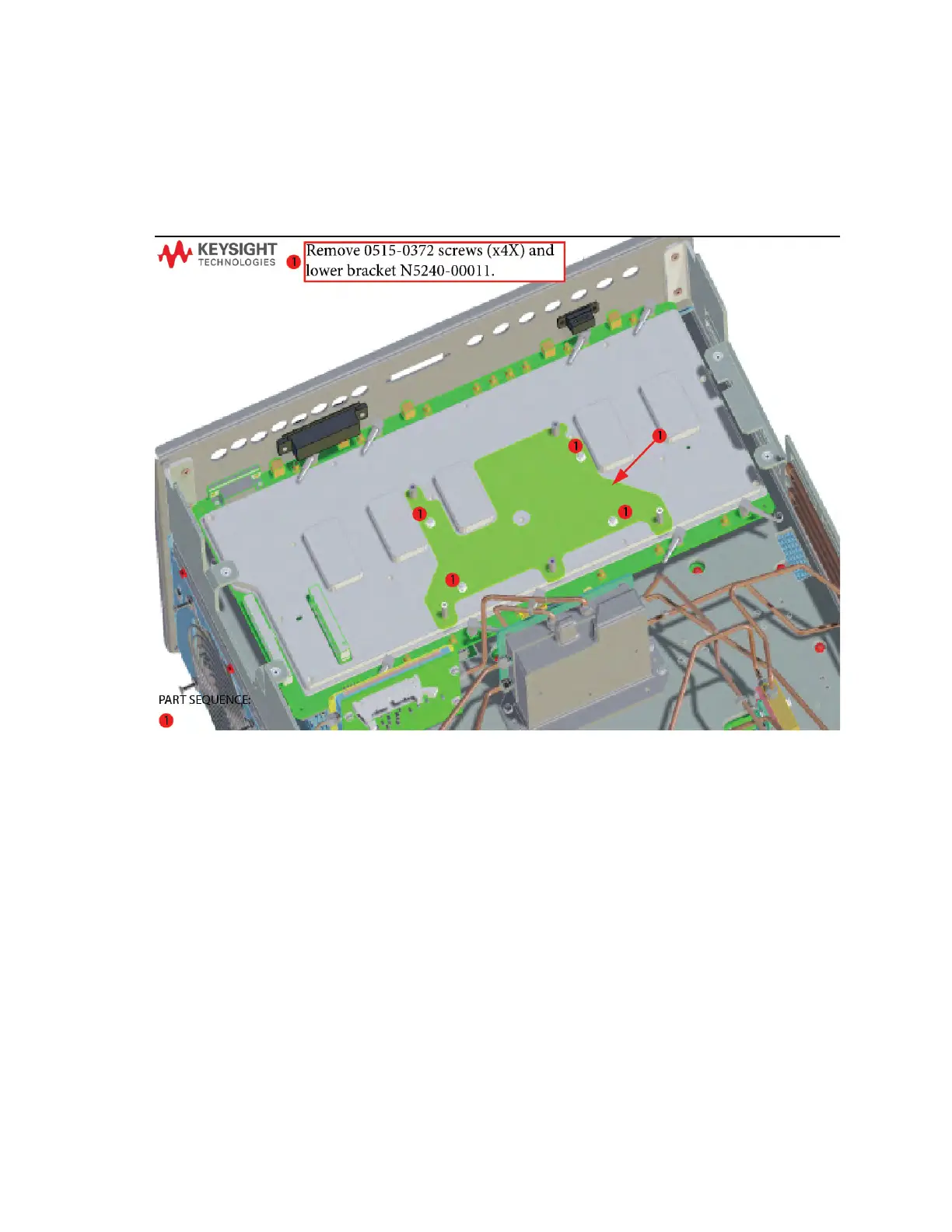
24
Step 12. Remove Some Bottom-Side Semi-Rigid Test Set Cables
25
Step 13. Remove the A23 Mixer Brick Assembly
26
Step 14. Assemble the A24 Mixer Brick and A22 Splitter Assemblies
27
Step 15. Install the A23/A24 Mixer Brick Brick Assembly
29
Step 16. Assemble the A26 and A27 Receiver Bridge Assemblies
30
Step 17. Install the A26 and A27 Receiver Bridge Assemblies
30
Step 18. Assemble A35/A36 Source and A43/A44 Receiver Attenuators
31
Step 19. Install A35/A36 Source and A43/A44 Receiver Attenuators
32
Step 20. Assemble the A72 (Port 3) and A73 (Port 4) Bias Tee Combiner Assemblies
33
Step 21. Install the A72 and A73 Bias Tee Combiner Assemblies
34
Step 22. Assemble the A29 - A32 Test Port Coupler Assemblies
36
Step 23. Install the LED Boards and Test Port Coupler Assemblies On the 4-Port Test Set Front Plate
37
Step 24. Install the Bulkhead Connectors in the Test Set Front Plate
38
Step 25. Install the 4-Port Coupler Plate Assembly to the Deck
39
Step 26. Remove the Old A11 (x2) Direct Digital Synthesizer (DDS) Assembly and Cables
40
Step 27. Assemble the A5 and A8 26.5 GHz Source 1 and 2 Assemblies
42
Step 28. Install the A8 26.5 GHz Source 2 Assembly
43
Step 29. Install the *NEW* A11 (x4) Direct Digital Synthesizer (DDS) Assembly and Cables
44
Step 30. Connect New Cables to A20 IF Multiplexer (IF MUX) Board
48
Step 31. Reinstall A70 Low Frequency Extension (LFE) Board Bracket
48
Step 32. Install the New Mixer Brick (MXB) Cables and Route Cables
49
Step 33. Reconnect/Connect and Route Low Frequency Extension (LFE) Cables (8120-5014 (x2) and 8120-5017 (x3)) and the Other Ends of the Cables Connected to the IF Multiplexer (IF MUX) Board
51
Step 34. Install the New A70 Low Frequency Extension (LFE) Board
52
Step 35. Connect/Reconnect A71–A74 Bias-Tee Combiner’s Cables to A70 Low Frequency Extension (LFE) Board and the Other Ends of the New Cables Connected to the IF Multiplier (IF MUX) Board
53
Step 36. Install the Test Set Cables and Install Cable Clamps on Ferrite Beads
54
Step 37. Secure the Front Panel Bulkhead Connectors
70
Step 38. Reinstall the A19 Test Set Motherboard
70
Step 39. Install Cables on the A19 Test Set Motherboard
71
Step 40. Install/Reinstall the A71–74 Bias-Tee combiner’s Gray Low Frequency Extension (LFE) DC Bias Cables and Route Cables
72
Step 41. Install the Other End of the A70 LFE Board Cables to the A11 Direct Digital Synthesizer (DDS) Assembly Gray Cables
76
Step 42. Replace the Front Panel’s Lower Dress Panel
77
Step 43. Reinstall Front Panel Assembly
78
Step 44. Install the New Lower Front Panel Overlay
78
Step 45. Install the Front Panel Jumper Cables
78
Step 46. DC Continuity Test the LFE Board and Test Ports
79
Step 47. Position the Cables and Wires to Prevent Pinching
79
Step 48. Reinstall the Inner Cover
79
Step 49. Reinstall the Outer Cover
79
Step 50. Remove Option 220 License
80
Step 51. Enable Option 420
81
Step 52. Verify the PNA Analyzer Program is Running with the Correct Options
83
Step 53. Perform Post-Upgrade Adjustments and Calibration
84
Step 54. Prepare the PNA for the User
86
4
Based on 1 rating
Ask a question
Give review
Questions and Answers:
Need help?
Do you have a question about the Keysight Technologies N5222B and is the answer not in the manual?
Ask a question
Keysight Technologies N5222B Specifications
General
Brand
Keysight Technologies
Model
N5222B
Category
Measuring Instruments
Language
English
Related product manuals
Keysight Technologies N5221B
88 pages
Keysight Technologies N5224A
36 pages
Keysight Technologies N5221A
368 pages
Keysight Technologies N5249A
36 pages
N5250C PNA Series
79 pages
N5290/1A PNA Series
88 pages
Keysight Technologies N9000B
20 pages
Keysight Technologies EXA N9010B
27 pages
Keysight Technologies N9010B-526
617 pages
FieldFox N9914A
756 pages
FieldFox N9938A
756 pages
FieldFox N9917A
756 pages