N9030B PXA Signal Analyzer Service Guide 445
Assembly Replacement Procedures
RF Area (Options 503, 508, 513, 526)
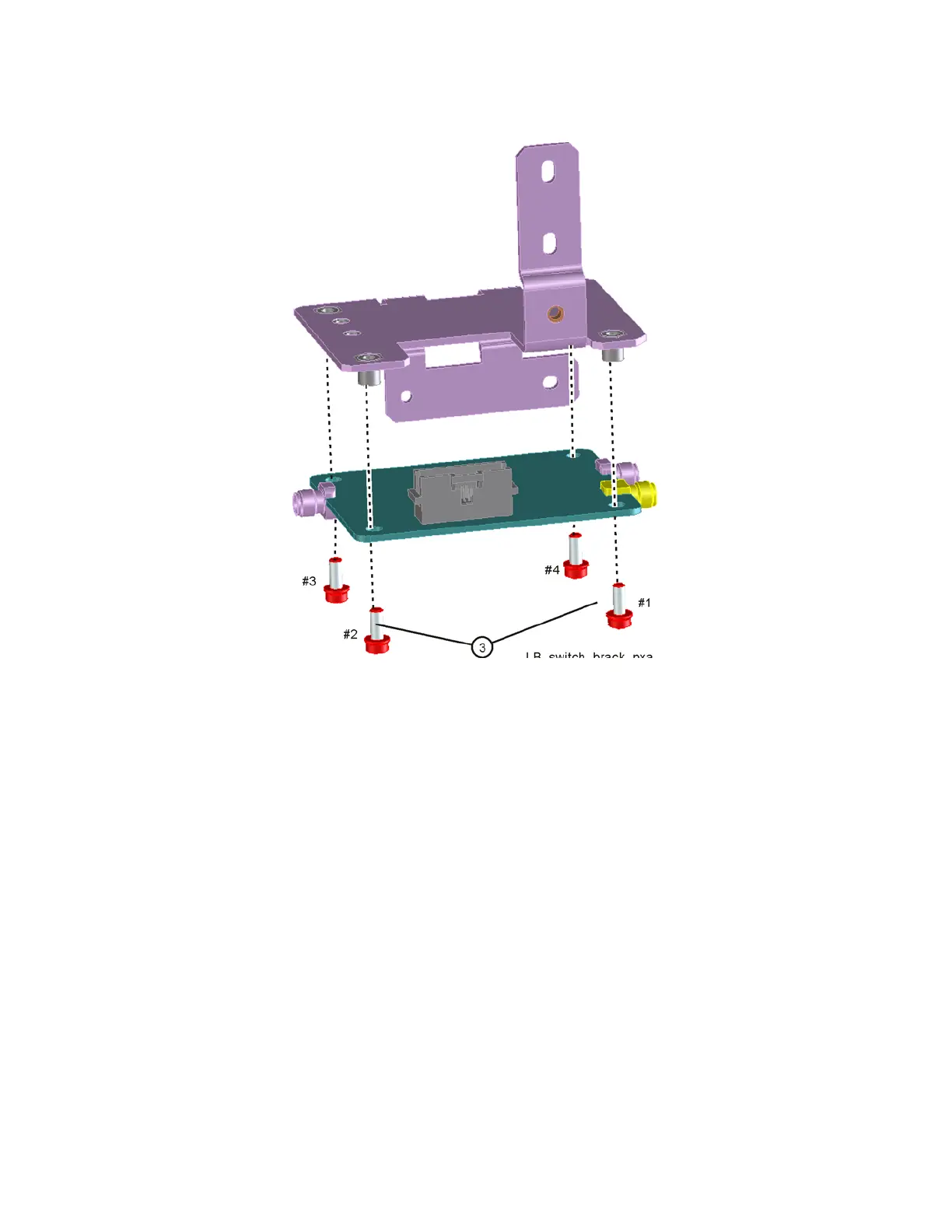
Figure 16-11 Low Band Switch and Bracket Separation
Replacement
1. Refer to Figure 16-11. Place the switch onto the bracket and replace the
four screws (3) (0515-0372). Torque to 9 inch-pounds in the sequence
shown, starting with #1.
2. Place the switch/bracket into place into the chassis and replace the two
screws (0515-0372). Torque to 9 inch-pounds starting with the screw
closest to the front of the instrument.
3. Refer to Figure 16-9. Replace the semi-rigid cables W6, W8, and W56.
Torque to 10 inch-pounds.
4. Replace the ribbon cable W7. Ensure locking tabs on the sides of the
connector are engaged.
5. Refer to Figure 16-7. Position the RF bracket onto the chassis and replace
the sixteen screws (0515-0372). Torque to 9 inch-pounds.
6. Replace the front panel. Refer to the Front Frame Assembly replacement
procedure.
7. Replace the instrument outer case. Refer to the Instrument Outer Case
replacement procedure.

 Loading...