N9030B PXA Signal Analyzer Service Guide 493
Assembly Replacement Procedures
RF Area (Options 544, 550)
Replacement
1. Refer to Figure 16-60. Attach switches (2)and (4) to bracket with three
screws 0515-1934 for each switch. Note that the switch with the wire
pigtail (4) mounts below the switch without the pigtail (2). Torque to 6
inch-lbs.
2. Place the switch/bracket assembly into the frame and secure with the two
screws 0515-2032. Torque to 9 inch-lbs.
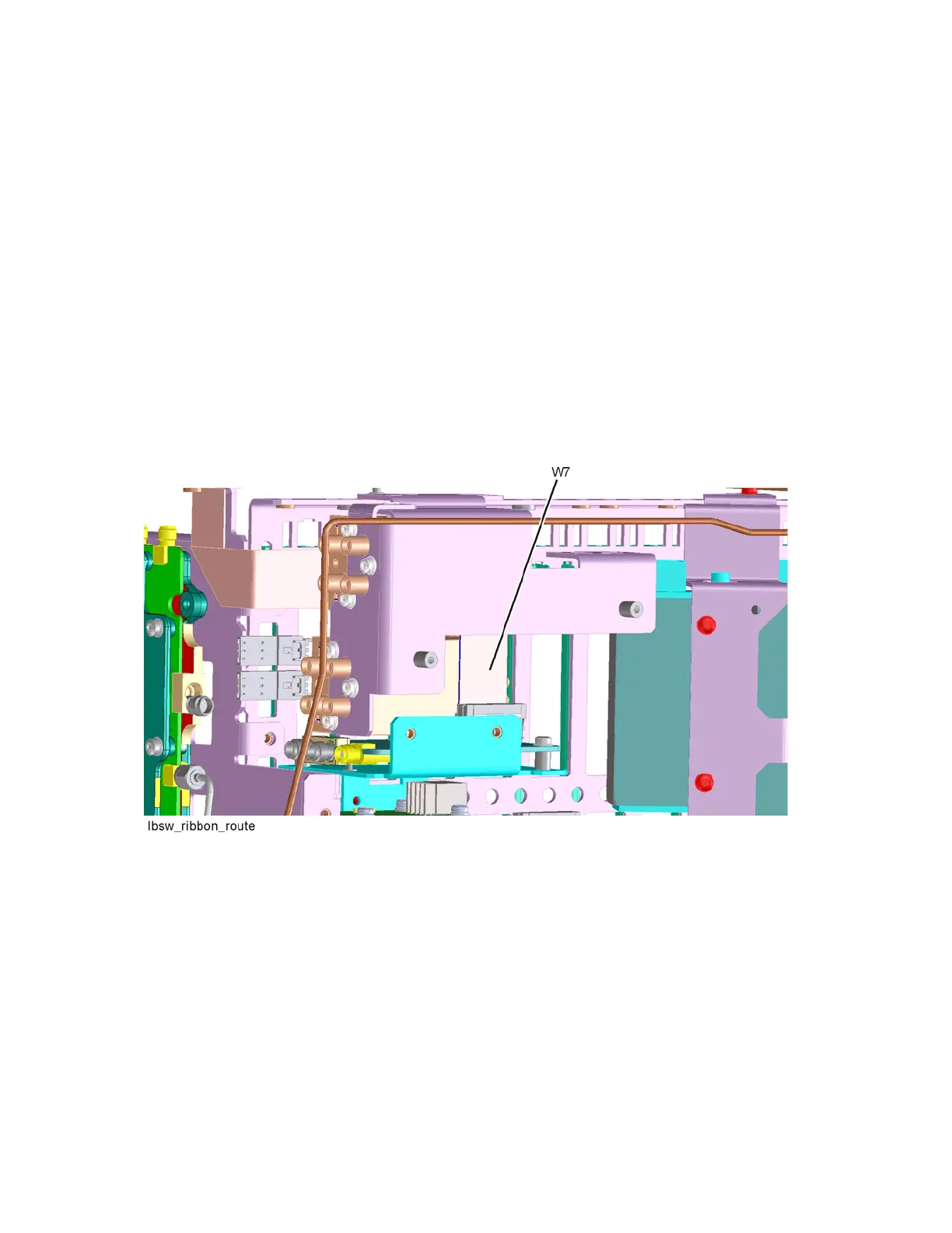
3. Refer to Figure 16-61. Route W7 in between the two switches as shown
and insert W7 connector into Low Band Switch header. Ensure the locking
tabs are engaged on both sides of the connector.
Figure 16-61 W7 Routing

 Loading...