Keysight B1500A Configuration and Connection Guide, Edition 6 3-27
Connection Guide for Wafer Prober
Interlock circuit
4. Use wire to connect the two switches in series between pin number 1 and 2 (or 3) of the
interlock connector. See Figure 3-28.
5. Use wire to connect the LED between pin number 4 and 5 (or 6) of the interlock
connector. See Figure 3-28.
6. Attach the interlock connector to the mounting hole.
If Keysight B1500A Interlock connector is connected to the interlock circuit, Keysight
B1500A SMU cannot force more than ± 42 V when the door is open. When the door is
closed, it can force more than ± 42 V.
When more than ± 42 V is forced from an SMU, the LED lights to indicate high voltage
output.
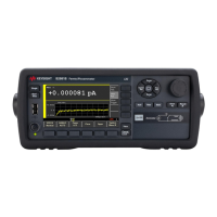
Figure 3-29 Dimensions of the LED (Keysight part number 1450-0641)
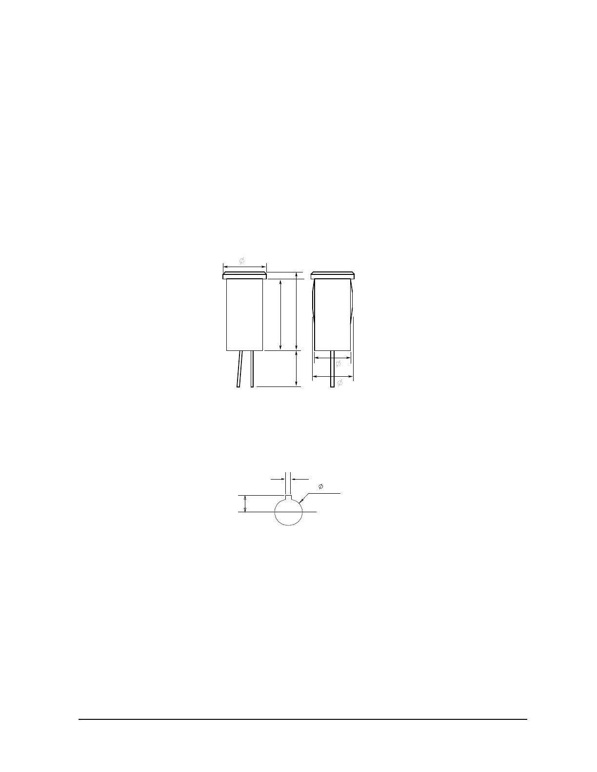
Figure 3-30 Dimensions of Mounting Hole for the Interlock Connector
6
10
11
5
5.6
5
Units: mm
Anode (+)
Cathode (-)
 Loading...