Electronic Calibration Modules Reference Guide 4-11
Use, Maintenance, and Care of the Devices
Gaging Connectors
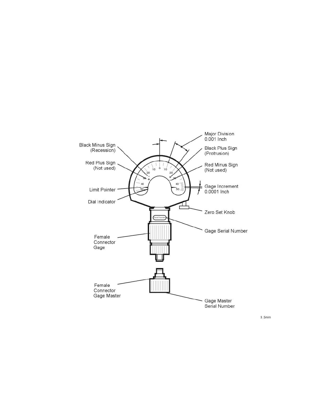
When making a measurement, the gage dial indicator will travel in one of two
directions. If the center conductor is recessed from the zero reference plane,
the indicator will move counterclockwise to determine the amount of
recession, which is read as a negative value. If center conductor protrudes, the
indicator will move clockwise to measure the amount of protrusion, which is
read as a positive value. Refer to “Typical Pin Depth Values” on page 5-21 for
definitions of protrusion and recession.
Figure 4-3 Typical Gage: 1.85 mm, 2.4 mm, 2.92 mm, and 3.5 mm Connectors