1 Calibration Procedures
96 Keysight U3606B Service Guide
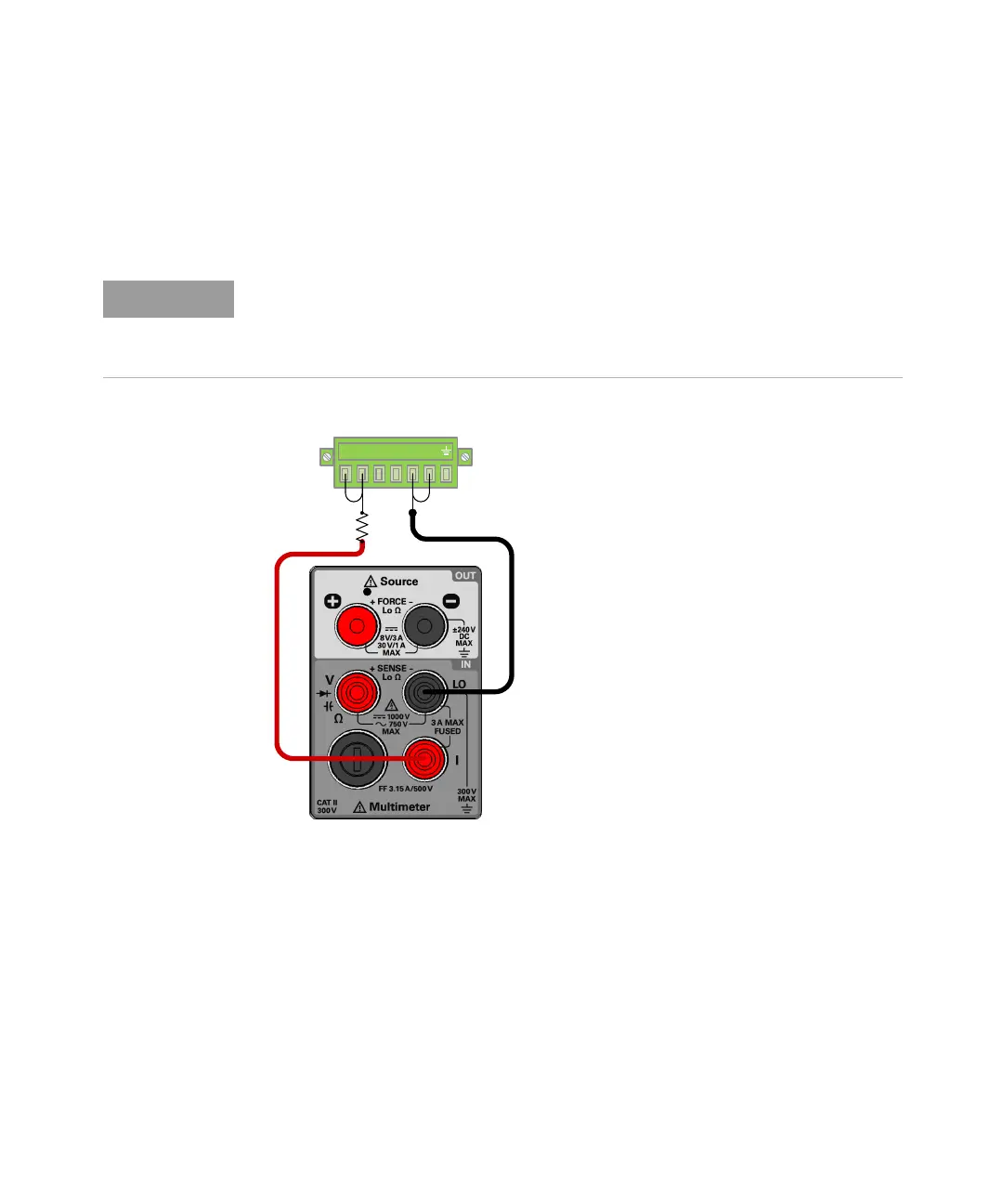
For adjustment item “LOAd1”, “LOAd2”, “LOAd3”, and “LOAd4”, connect an
additional fixed resistor across the front panel + rear output terminal and the I
(red) terminal according to the fixed resistors value on Table 1-32. Leave the –
rear terminal and LO (black) terminal connected.
5 Verify the constant current adjustments using the “CC programming and
readback accuracy” on page 56.
Do not remove the short bar between the rear panel sense terminals (+S and –S)
are the rear panel output (+ and –) terminals. See Chapter 3 of the U3606B
User’s Guide, “Remote sensing connections,” starting on page 116 for more
information on how to connect the load leads.