2
Assemble units as described herein only. To do otherwise
may result in instability. All screws, nuts and bolts must be
tightened securely and must be checked periodically after
assembly. Failure to assemble properly, or to secure parts
may result in assembly failure and personal injury.
WorkUp
®
Adjustable Table - Model CB
Assembly Instructions
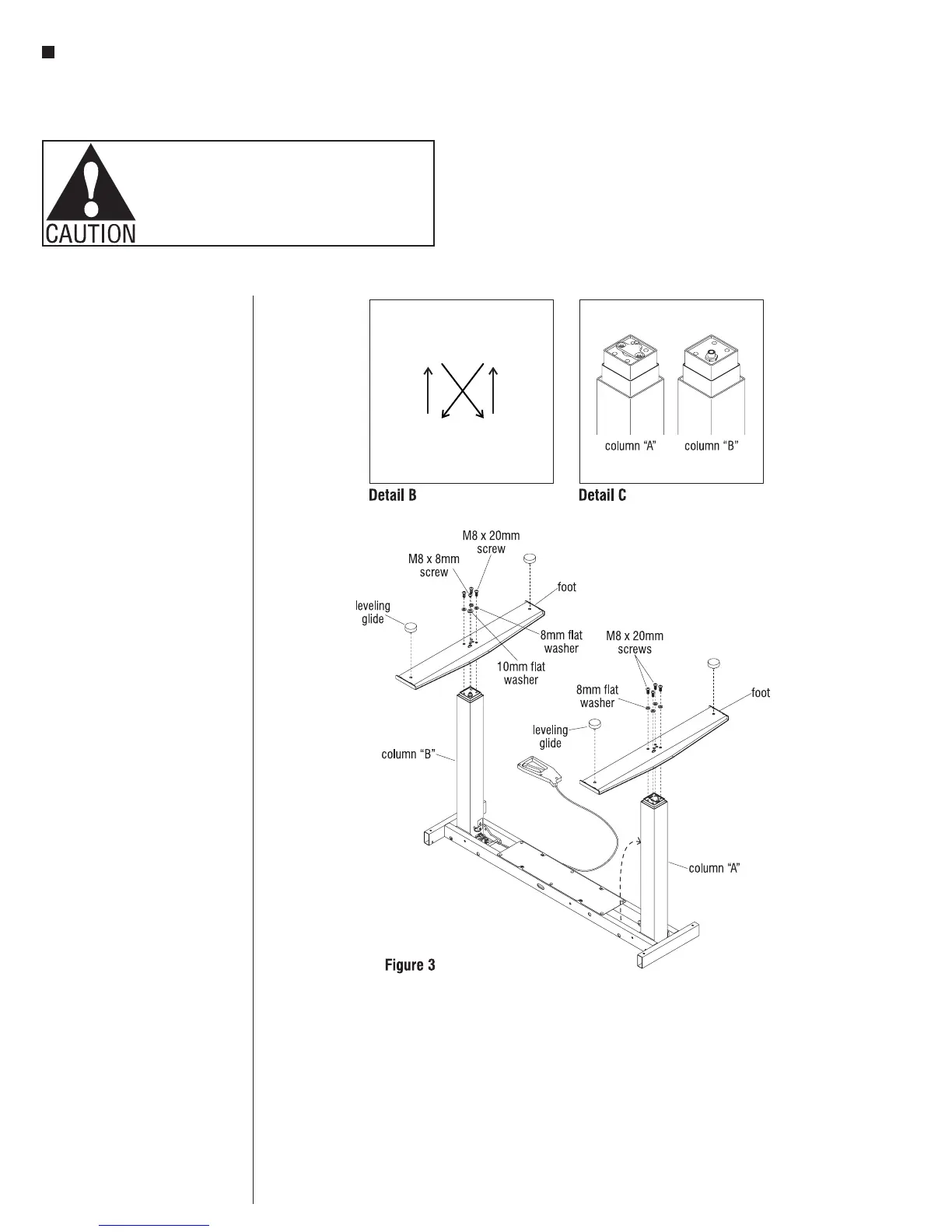
Note: When tightening the M8
screws into the top of the column,
start by twisting in all four screws
“finger tight”. Then tighten the
screws one quarter turn at a time
using a diagonal tightening pattern
as shown in Detail B. Repeat the
diagonal pattern until all four screws
are tight.
Note: Refer to Detail C to identify
columns “A” and “B”.
Foot to Base Assembly,
Column “A”
1. With the base inverted, place a foot
over the end of column “A” so the
column fits into the square hole in
the foot. The holes in the foot should
line up with the four holes in the
column end. The short threaded rod
that protrudes from the column end
should also line up with a hole in
the foot. If not the foot needs to be
removed and repositioned (Figure 3
& Detail C).
2. Attach the foot using four
M8 x 20mm screws and four 8mm
flat washers (Figure 3).
Note: If the roller foot option was
purchased, one foot will have
pre-assembled rollers.
3. Thread a leveling glide into the holes
at the ends of the foot (Figure 3).
Foot to Base Assembly,
Column “B”
1. Place a foot over the end of column
“B” so the column fits into the square
hole in the foot. The holes in the foot
should line up with the three holes
and special nut in the column end.
If not, the foot needs to be removed
and repositioned (Figure 3 &
Detail B).
2. Attach the foot using three
M8 x 20mm screws with three 8mm
flat washers, and one M8 x 8mm
screw with one 10mm flat washer
(Figure 3).
3. Thread a leveling glide into the holes
at the ends of the foot (Figure 3).