24
Assemble units as described herein only. To do otherwise
may result in instability. All screws, nuts and bolts must be
tightened securely and must be checked periodically after
assembly. Failure to assemble properly, or to secure parts
may result in assembly failure and personal injury.
Seminar
TM
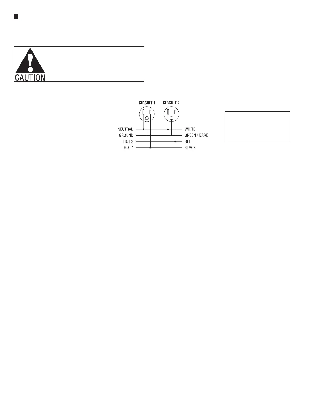
Tables with 4-Wire Power System - 4-Wire Diagram
Assembly Instructions
WARNING:
Risk of fire or electrical shock. Do not
electrically connect span connectors to more
than one supply source. Always determine that
the span connectors are electrically connected
to one and only one source of supply.
Specifying Power on Seminar
Tables
Specifics of the 4-wire system - 4-wire,
2 circuit system includes:
• (2) hot wires (circuits 1 & 2 share
the ground and neutral wire)
• (1) ground wire
• (1) neutral wire
Each circuit is rated for 20 amps but
NEC recommends utilizing only 80% or
16 amps per circuit
(16 amps x 2 circuits = 32 total amps).
Power Infeeds
Determine quantity of power infeeds.
1. One infeed per row provides
power for up to eight shared power
modules with USB, or sixteen seats
(16 seats x average of 2 amps per
computer = 32 total amps).
2. If rows have more than sixteen
seats, a second infeed will be
required.
3. If the number of circuits per row is
more than two, a second infeed will
be required in that row.
a. Determine the total amperage per
row (refer to back of the computer).
b. Determine the number of circuits
required per row (total amperage
per row divided by 8).
4. Determine location of power
infeeds. Infeeds can come up any
fixed table base.
5. Connection is typically made at
a (user supplied) junction box
outside the nearest leg. Power
infeeds can come directly through
bottom of base, but locations must
be exact.
 Loading...


