8
Assemble units as described herein only. To do otherwise
may result in instability. All screws, nuts and bolts must be
tightened securely and must be checked periodically after
assembly. Failure to assemble properly, or to secure parts
may result in assembly failure and personal injury.
Seminar
TM
Tables with 4-Wire Power System - Receptacles
Assembly Instructions
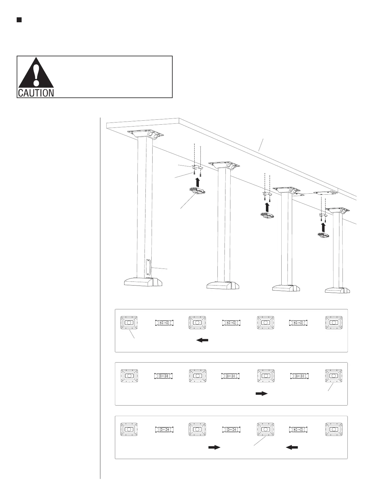
Figure 6
Figure 7
duplex
receptacle
future
power infeed
power
infeed location
power
infeed location
ground prong faces
ground prong faces
ground prong faces
ground prong faces
Left-Hand Single Direction Infeed
Right-Hand Single Direction Infeed
Two-Direction Infeed
power
infeed location
#x /”10
3
4
screw
receptacle
mounting
mount
tabletop
Receptacles Installation
Note: All table connections (joint
fasteners and splice plates) must be
securely fastened before electrical
components can be installed.
Important: Duplex receptacles
must install correctly oriented to
the power infeed they will receive
power from. The single ground
prong must always orient toward
the power infeed. If this is not done,
disassembly and re-assembly will
be required.
12. Position the receptacle mounting
brackets up to the pre-drilled
mounting holes as illustrated, and
secure each using two #10 x
3
/
4
”
screws per bracket. Torque screws
to 25 in/lb (Figure 6).
13. Reference the space-planning
layout and determine where the
power infeed(s) are located, and
which direction the power will run
on the length of tabletops before
installing duplex receptacles.
Position each duplex receptacle
with the single ground prong
oriented toward the associated
power infeed. Then snap each
receptacle into place on the
receptacle mounting brackets
(Figures 6 & 7).
14. Continue following steps 1 & 2
closely to install all remaining
duplex receptacles (Figures 6 & 7).