9
Assemble units as described herein only. To do otherwise
may result in instability. All screws, nuts and bolts must be
tightened securely and must be checked periodically after
assembly. Failure to assemble properly, or to secure parts
may result in assembly failure and personal injury.
Seminar
TM
Tables with 4-Wire Power System - Single-Direction Power Infeed & Jumpers
Assembly Instructions
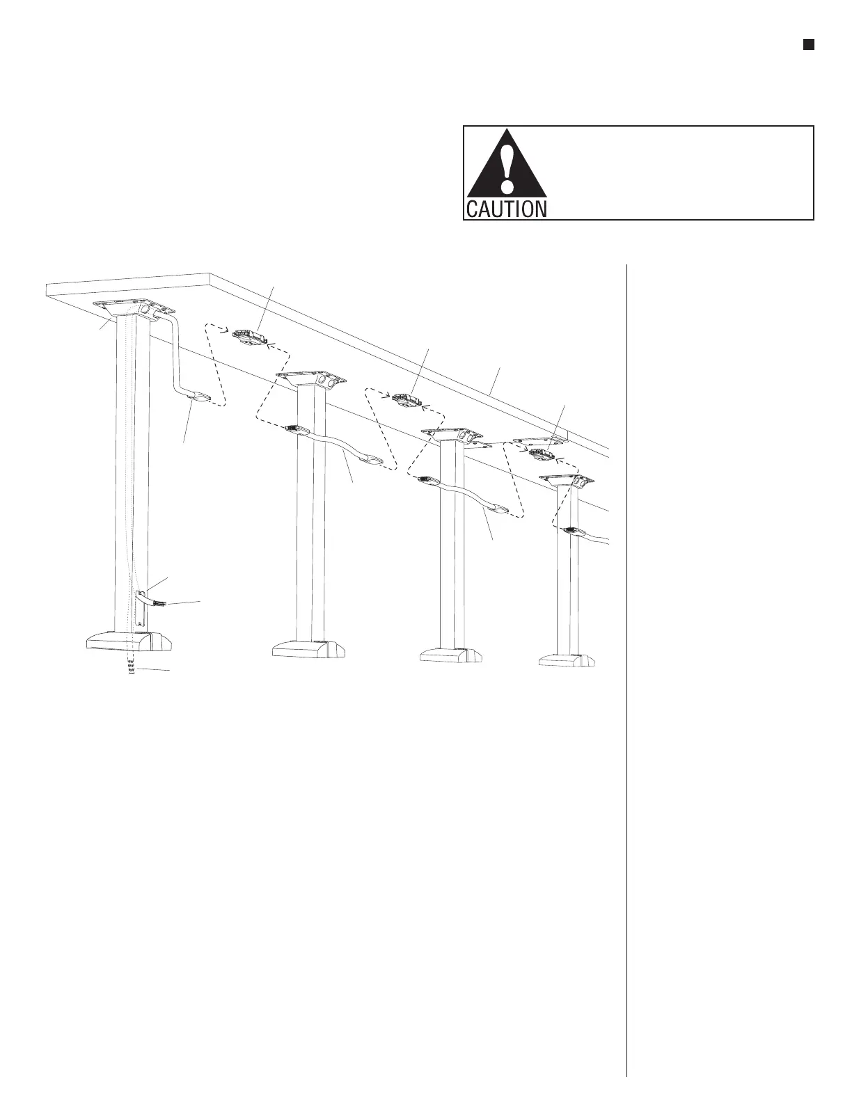
Figure 8 - Power Infeed Single Direction (right-hand or left-hand)
lower wire
access hole
duplex
receptacle
duplex
receptacle
duplex
receptacle
receptacle
jumper
receptacle
jumper
tabletop
mounting ange
power infeed
(exposed end)
power infeed
(run from below oor level)
tabletop
single-direction
power infeed
plug end
Single-Direction Power Infeed
Installation
Note: All table connections (joint
fasteners and splice plates) must be
securely fastened before electrical
components can be installed.
Note: Refer to the space-planning
layout for power infeed location.
The instructions below cover
single-direction power infeed with
receptacle jumpers. See pages
11 & 12 for two-direction power
infeed, which uses the same power
infeed but adds a quad block to
direct power two ways.
15. Reference the space-planning
layout and determine the table base
location for the single-direction
power infeed. Check and assure
that the duplex receptacles are
installed correctly (Page 8,
Figures 6 & 7). The ground prongs
must be oriented to the side of the
associated power infeed. If below
floor level power is to be run to the
tabletops, the power infeed should
already be in place. To install above
floor level power infeed, run the
exposed wires end of the power
infeed through the oval cut-out in
the tabletop mounting flange, down
the table base column and out the
lower wire access hole, then plug
the connector end into the first
duplex receptacle next to the power
infeed (Figure 8).
16. Verify that the power infeed’s
exposed wire ends will reach their
desired connection location at floor
level. Do not attach power infeed to
any source power until instructed to
at a later time (Page 18, Figure 18).
17. Per the space-planning layout,
locate the required receptacle
jumpers and connect each end into
the installed duplex receptacles
under the tabletop (Figure 8).
 Loading...