10
Assemble units as described herein only. To do otherwise
may result in instability. All screws, nuts and bolts must be
tightened securely and must be checked periodically after
assembly. Failure to assemble properly, or to secure parts
may result in assembly failure and personal injury.
Seminar
TM
Tables with 4-Wire Power System - Single-Direction Receptacle Hub Shrouds
Assembly Instructions
Single-Direction Power Infeed
Installation (cont.)
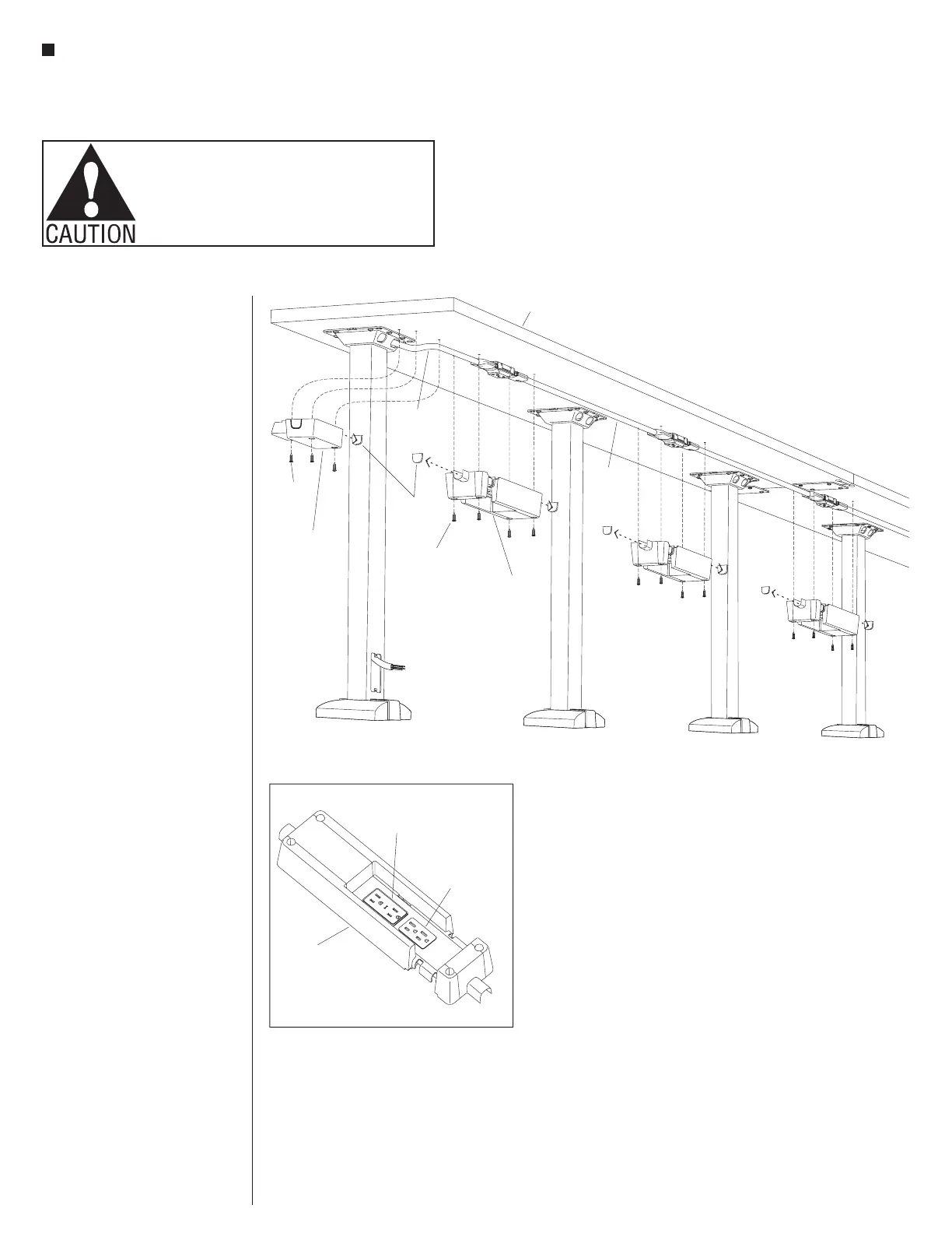
18. Orient each receptacle hub shroud
so the “receptacle orientation
marking” at the underside of the
shroud matches the orientation
of the correctly installed duplex
receptacles under the tabletop.
Remove jumper knock-outs from
ends where power cables will
run through, then position each
receptacle hub shroud up correctly
over the receptacle and secure
using four #10 x
3
/
4
” screws as
illustrated (Figure 9 & Detail E).
19. At the power infeed location, a
single-direction infeed shroud
must be installed. Depending on
the direction that the power runs,
either a right- or left-side knock
out must be removed. Position the
infeed shroud as illustrated over the
power infeed and against the table
mounting flange and secure to the
underside of the table using three
#10 x
3
/
4
” screws (Figure 9).
Figure - Power Infeed Single-Direction Shroud (right-hand or left-hand)9
receptacle
hub shroud
jumper
knock out
single-direction
infeed
shroud
single
direction
infeed
receptacle
jumper
#x /”10
3
4
screw
#x /”10
3
4
screw
tabletop
Detail E
duplex
receptacle
receptacle
orientation
marking
receptacle
hub shroud